
0.1 - 3.5GHz Prescaler
The prescaler circuit consists of several key components, including a high-frequency input stage, a frequency division stage, and an output stage. The input stage is typically designed to accommodate high-frequency signals, ensuring that the circuit can effectively process signals up to 3.5 GHz. This may involve the use of RF amplifiers or impedance matching networks to optimize signal fidelity.
The frequency division is achieved through a combination of flip-flops or counters that are configured to divide the input frequency by 1000. For instance, a series of binary counters can be employed, where each stage divides the frequency by 2, ultimately achieving the desired division ratio. The choice of components in this stage is critical, as they must operate efficiently at high frequencies while maintaining low phase noise and minimal signal distortion.
The output stage is responsible for converting the divided frequency output into a format suitable for measurement. This may involve additional filtering to remove harmonics and noise, ensuring that the output signal is clean and stable. The final output frequency of 3.5 MHz can then be easily measured using standard frequency meters, making the prescaler a valuable tool in various RF applications, including communications and signal analysis.
Power supply considerations are also essential in the design of this prescaler. A stable power supply is required to ensure that the circuit operates reliably across its specified frequency range. Additionally, proper grounding and layout techniques must be employed to minimize electromagnetic interference and ensure optimal performance. Overall, the prescaler is a crucial component for frequency management in high-frequency applications.This handy prescaler divides input frequency by 1000. It takes maximum input frequency of 3. 5GHz and converts it into 3. 5MHz that may be measured using standard frequency meter. 🔗 External reference
Related Circuits
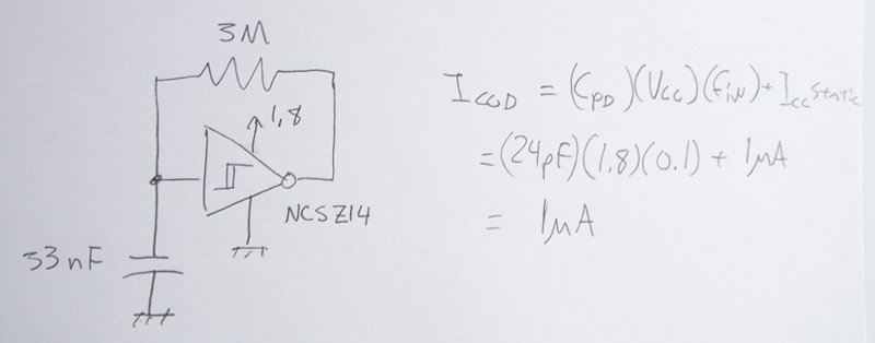
The power supply varies, and the circuit must operate at under 10 µA of current (excluding the capacitor charging). It triggers a Silicon Controlled Rectifier (SCR) every 10 to 30 seconds as long as the power supply is above...
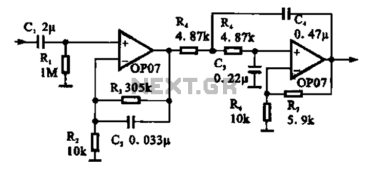
Broadband 0.1 to 10 Hz filter amplifier. The broadband circuit consists of two operational amplifiers configured as filter amplifiers operating in the frequency range of 0.1 to 10 Hz. The broadband filter amplifier circuit utilizes two operational amplifiers (op-amps) to...
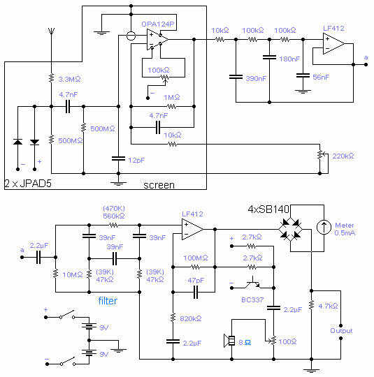
The frequency covered is from 0.1Hz to 10Hz and useful signals are received up to 16Hz. The first Op-Amp, properly shielded, must be installed close to the antenna (1-3m long) and connected to the rest of the circuit with...
0.1V to 50V Variable Power Supply Circuit Diagram. Features: the lowest current limit is 0.6 ampere, opamp CA3130 compares the reference voltage. The variable power supply circuit is designed to provide an adjustable output voltage ranging from 0.1V to 50V,...
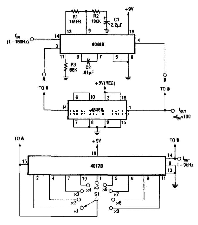
For multiplying frequencies in the 1 to 150 Hz range, this circuit utilizes a 4046B phase-locked loop (PLL) and a 100 prescaler. The output from the voltage-controlled oscillator (VCO) is phase-locked to the low-frequency input. This configuration facilitates the...
These parameters are expected with an approximately 50% square wave up to frequencies of several MHz, and symmetric sine waves at higher frequencies. The primary limitation is based on the maximum clocking rate specification for the MM74HC6040 ripple counter...
Warning: include(partials/cookie-banner.php): Failed to open stream: Permission denied in /var/www/html/nextgr/view-circuit.php on line 713
Warning: include(): Failed opening 'partials/cookie-banner.php' for inclusion (include_path='.:/usr/share/php') in /var/www/html/nextgr/view-circuit.php on line 713