
12V/20W Stereo Amplifier
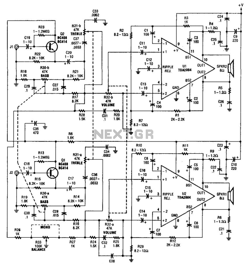
The described amplifier circuit operates in a bridged configuration, which effectively doubles the voltage across the load, resulting in increased power output to the speakers. This configuration requires careful attention to ensure that both output terminals are above ground potential, which is critical for safe operation and to prevent short circuits.
The input sensitivity of 300 mV indicates the minimum voltage required at the input to achieve the rated output power of 20 W per channel. This specification is particularly important for compatibility with various audio sources, ensuring that the amplifier can be driven adequately without distortion.
The use of a +12 V power supply is standard for many audio amplifiers, as it provides a sufficient voltage level while maintaining a manageable heat output. However, the specification that components U1 and U2 must be heatsinked is crucial, as these components likely handle significant power dissipation during operation. Proper thermal management will enhance the reliability and longevity of the amplifier.
In terms of circuit design, it is essential to include adequate bypass capacitors near the power supply pins of the amplifier ICs to filter out noise and stabilize the voltage supply. Additionally, appropriate feedback networks should be implemented to ensure linear operation and minimize distortion.
Overall, this amplifier circuit is designed for efficient audio amplification with a focus on performance and reliability, making it suitable for various audio applications where moderate power output is required. This amplifier delivers 20 W per channel. Input sensitivity is about 300 mV into 47 kii. Notice that a bridged o utput is used, so the speakers are operated with both wires above ground. A +12-V supply is used. U1 and U2 must be heatsinked. 🔗 External reference
Related Circuits
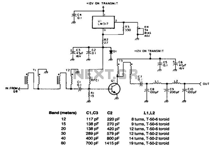
This linear amplifier provides a 10-W PEP output with a 1.25-W drive on the 10 m band. The transformers, T1, T2, and T3, consist of 10 turns of bifilar windings on an FT-50-43 toroidal core and are designed for...
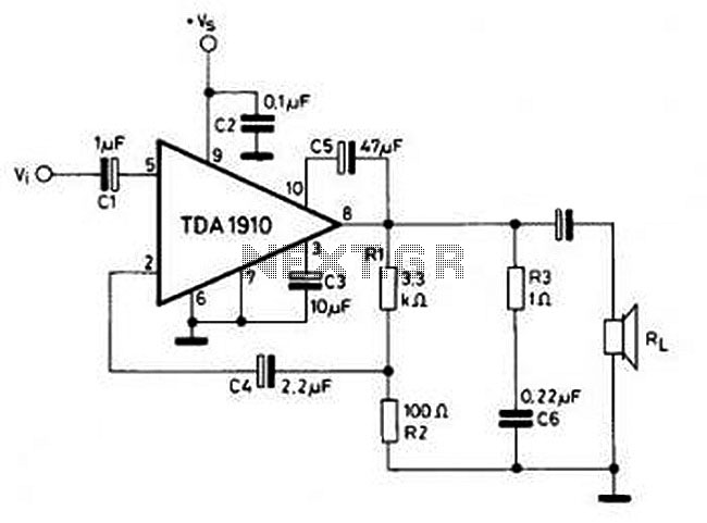
This circuit is simple and inexpensive, which is its primary advantage. Although the output power is not high, the audio quality is good due to the TDA1910's very low noise feature. This circuit is suitable for use as a...
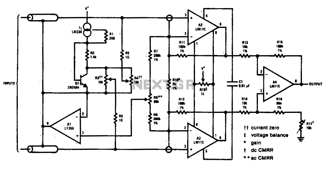
This circuit includes input guarding, cable bootstrapping, and bias current compensation. Differential bandwidth is reduced by Cl, which also makes common-mode rejection less dependent on the matching of input amplifiers. The described circuit features several critical components designed to enhance...
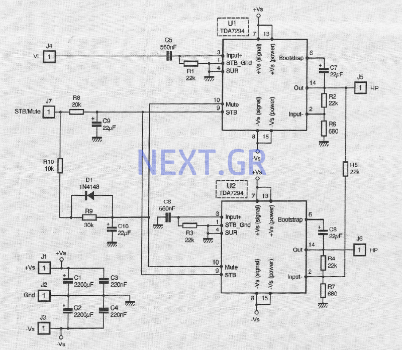
The TDA 7294 from T-MICROELECTRONICS is a monolithic integrated circuit housed in a "Multiwatt 15" package, primarily designed for use in Class AB amplifiers for high-fidelity applications, including stereo systems, active speakers, and television receivers. Its large feed area...
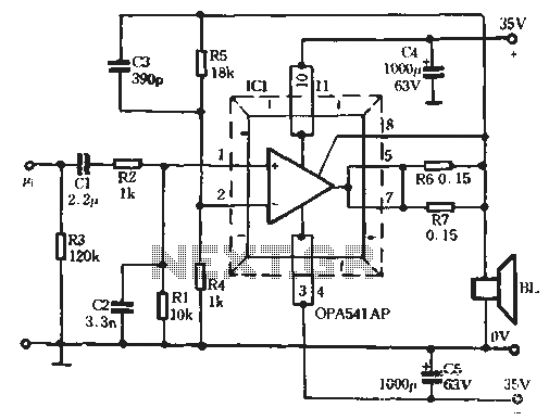
The Burr-Brown OPA541 chip is a power amplifier capable of operating with a maximum power supply voltage of 40V, delivering a continuous output current of up to 5A. The output current can be adjusted using an external resistor to...
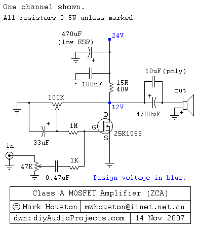
This weblog discusses electronic circuit schematics, PCB design, DIY kits, and electronic project diagrams. It features a simple Class A MOSFET amplifier using the 2SK1058 component. The circuit operates with a 24V supply voltage at high current. It incorporates...
Warning: include(partials/cookie-banner.php): Failed to open stream: Permission denied in /var/www/html/nextgr/view-circuit.php on line 713
Warning: include(): Failed opening 'partials/cookie-banner.php' for inclusion (include_path='.:/usr/share/php') in /var/www/html/nextgr/view-circuit.php on line 713