
1KHz Sine wave Generator
The circuit utilizes an inverted Wien bridge oscillator, which is a well-established method for generating sine waves. The core of the circuit comprises two capacitors (C1 and C2) and four resistors (R3 and R4) configured to create a feedback loop that stabilizes the oscillation frequency at 1 kHz. The use of precision components in the feedback network is crucial for minimizing distortion and ensuring a clean sine wave output.
The variable output feature allows for adjustments in amplitude, which is essential for testing various audio equipment without exceeding their input limits. The low output impedance is significant as it enables the circuit to drive loads effectively, maintaining signal integrity even when connected to multiple devices or under varying load conditions.
Incorporating a small filament bulb serves a dual purpose: it acts as a stabilizing element in the circuit and provides visual feedback on the output amplitude. As the output amplitude varies, the filament bulb's brightness changes correspondingly, allowing the user to monitor the output level easily.
This sine wave generator is particularly useful for testing high-fidelity audio devices, such as the Precision Audio Millivoltmeter and the Three-Level Audio Power Indicator. By providing a stable sine wave signal, the circuit facilitates the evaluation of frequency response, distortion characteristics, and overall performance of audio circuits, making it an invaluable tool in audio engineering and testing environments.This circuit generates a good 1KHz sinewave adopting the inverted Wien bridge configuration (C1-R3 & C2-R4). It features a variable output, low distortion and low output impedance in order to obtain good overload capability.
A small filament bulb ensures a stable long term output amplitude waveform. Useful to test the Precision Audio Millivoltmeter, Three-Level Audio Power Indicator and other audio circuits posted to this website. 🔗 External reference
Related Circuits
A PLL oscillator, or phase-locked loop oscillator, is a control method that compares a controlled system or plant to a reference signal. A phase-locked loop (PLL) oscillator is a sophisticated electronic circuit designed to synchronize an output signal's phase and...
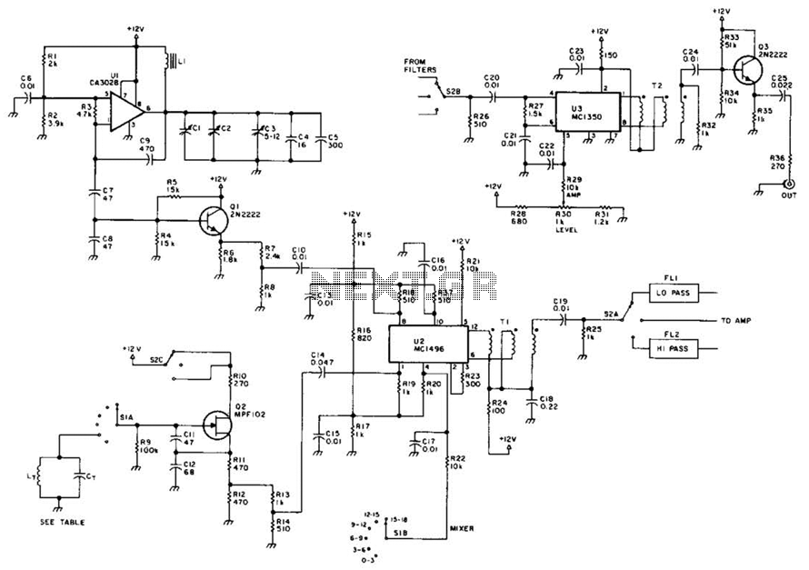
This circuit utilizes a voltage-controlled oscillator (VFO) operating in the frequency range of 15 to 18 MHz (U1), which feeds into a balanced mixer (U2). A fixed oscillator signal is combined with the VFO output to produce an output...
Quartz crystals exhibit a property where their amplitude and phase characteristics repeat at uneven multiples of their fundamental frequency. Overtone crystals are specifically cut to enhance this property. Any crystal can be utilized at one or more of its...
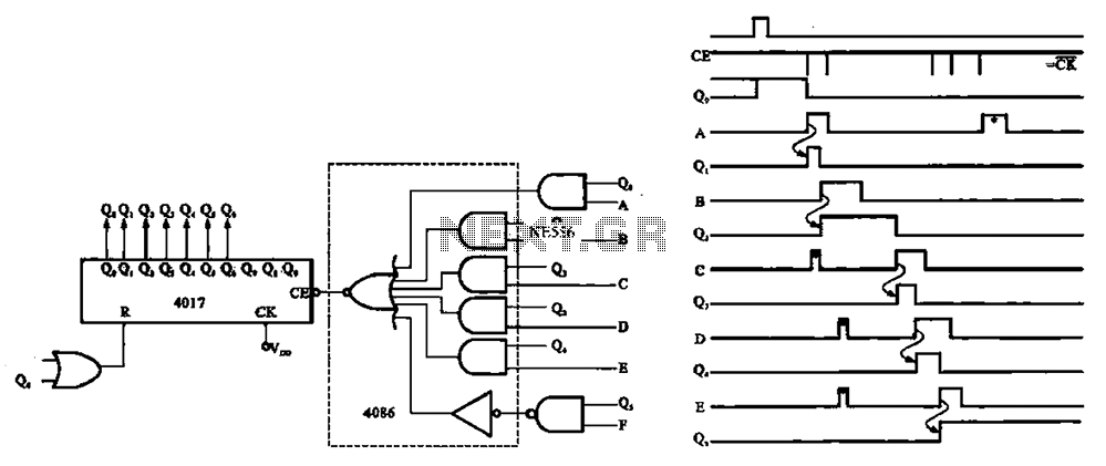
An asynchronous counter is illustrated in this circuit. It operates without a clock synchronization signal, making it suitable for use in a random counter or as an independent unit circuit. An asynchronous counter, also known as a ripple counter, is...
The telephone ring generator illustrated below produces the necessary high voltage using a simple switching mode power supply (SMPS) that incorporates a CMOS Schmitt Trigger square wave oscillator, a 10 mH inductor, a high voltage switching transistor (such as...
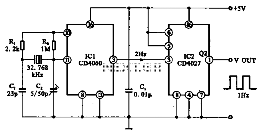
A 1Hz clock signal generator circuit is presented, which demonstrates a sophisticated clock signal generating mechanism. This circuit can be utilized for digital clocks and timing applications. It comprises a binary counter (CD4060), a JK flip-flop (CD4027), and a...