
Ac/Dc Indicator
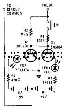
The described circuit employs two transistors configured as switches to control the illumination of two LEDs based on the nature of the input signal. The transistors are arranged to respond to voltage levels indicative of positive and negative DC signals, as well as alternating current (AC) signals.
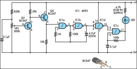
In this setup, the positive DC signal activates the first transistor, which in turn powers the red LED. Conversely, the second transistor is triggered by a negative DC signal, lighting the yellow LED. When an AC signal is present, the rapid alternation of voltage levels causes both transistors to switch on and off in a manner that results in both LEDs lighting up simultaneously.
The circuit can be designed using NPN or PNP transistors depending on the desired response characteristics. Resistors can be added in series with the LEDs to limit current and protect them from excessive voltage. Additionally, a diode may be placed in parallel with each LED to prevent reverse voltage from damaging the components when the signal polarity changes.
This circuit is particularly useful in applications where signal type identification is crucial, such as in audio signal processing, sensor outputs, or communication systems. The simplicity and effectiveness of this design make it an excellent choice for low-level signal detection and analysis. By using two switching transistors and two LEDs, this circuit can distinguish low-level ac and dc signals. If the red LED i lluminates, the signal is positive dc. If the yellow LED lights, the signal is negative dc. If the signal is ac, both LEDs will light. 🔗 External reference
Related Circuits
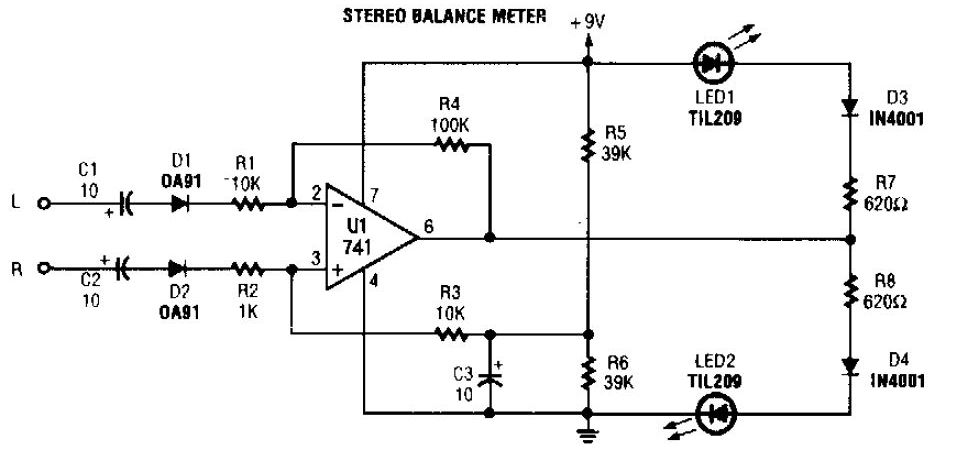
The simplest stereo balance meter circuit schematic available on the internet. When the left and right signals are equal, no output is present from U1 and pin. This stereo balance meter circuit is designed to visually indicate the balance between...
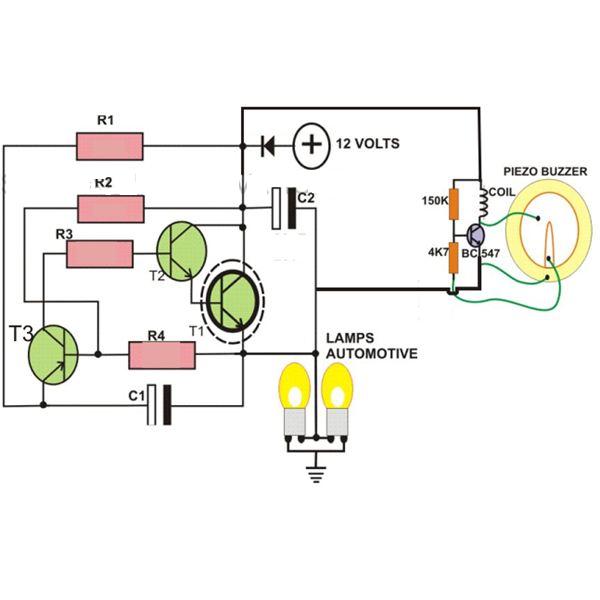
This circuit is designed to create a flasher unit for a motorbike. It is a simple turn signal flasher circuit that can be easily built and installed in any two-wheeler for the desired functionality. The circuit uses only two...
This simple and slightly unconventional circuit provides a clear indication of the supply voltage level in a larger device. When the indicator receives a stable 12 volts at its input, LED1 emits a steady yellow light that appears continuous...
This design integrates power-on and low-battery indication features, capable of operating with any battery voltage up to 15V. It has a very low current drain of 2mA or less and is cost-effective, priced under $3.50 with new components. When...

This device is a successor to the PIC16C71 4-digit LED frequency counter and voltmeter. It omits some hard-to-find components from the previous version that have been out of production for some time. The earlier PIC16C71 has been replaced with...

This circuit was utilized with an audio power amplifier to identify the point at which the output is -3 dB from maximum, indicated by LED D5, and at clipping, shown by LED D6. The indicator can be employed with...
Warning: include(partials/cookie-banner.php): Failed to open stream: Permission denied in /var/www/html/nextgr/view-circuit.php on line 713
Warning: include(): Failed opening 'partials/cookie-banner.php' for inclusion (include_path='.:/usr/share/php') in /var/www/html/nextgr/view-circuit.php on line 713