
Capacitance relay
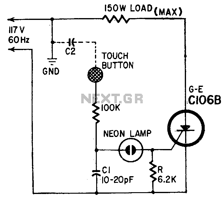
The described circuit utilizes capacitors Cl and C2 to create a capacitive touch sensing mechanism. In this configuration, Cl acts as the primary capacitor, while C2 represents the body capacitance of the user. The arrangement forms a voltage divider that influences the voltage levels present at the neon lamp and the SCR gate.
In the absence of a user, the capacitance C2 is relatively small compared to Cl, resulting in a voltage drop across Cl that is lower than the line voltage. When a user approaches the touch button, the effective capacitance C2 increases significantly due to the proximity of the user, effectively altering the voltage divider ratio. This change causes a larger voltage to develop across Cl, which is sufficient to trigger the neon lamp.
The SCR (Silicon Controlled Rectifier) gate is designed to respond to the discharge from Cl and C2. Once triggered, the SCR allows current to flow through the load, activating the connected device. The circuit's sensitivity can be fine-tuned by adjusting the value of Cl, making it possible to accommodate different user requirements or environmental conditions.
Furthermore, the area of the touch plate plays a critical role in the circuit's responsiveness. A larger touch plate area increases the capacitance and allows the circuit to detect the presence of an object without requiring direct contact. This feature enhances user experience and provides flexibility in applications where touch is not feasible. The design can be optimized for various applications by modifying the capacitance values and the physical dimensions of the touch plate.Capacitor Cl and body capacitance (C2>of the operator form the voltage divider from the hot side of the ac line to ground. The voltage across Cl is determined by the ratio of Cl to C2. The higher voltage is developed across the smaller capacitor. When no one is close to the touch button, C2 is smaller than Cl. When a hand is brought close to the button, C2 is many times larger than Cl and the major portion of the line voltage appears across Cl.
This voltage fires the neon lamp, Cl and C2 discharge through the SCR gate, causing it to trigger and pass current through the load The sensitivity of the circuit depends on the area of the touch plate. When the area is large enough, the circuit responds to the proximity of an object rather than to touch. Cl may be made variable so sensitivity can be adjusted. 🔗 External reference
Related Circuits
In the Fig.1, there exists a circuit, which is a sensitive switch that responds to AC signals of input, for signals above 5mV. It responds to all the signals from 50 Hz to 3 kHz, a region in which...
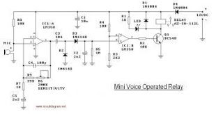
This circuit diagram represents a voice-operated relay. It functions similarly to a sound-activated switch circuit, which activates or deactivates the switch based on sound input. The output switch of this circuit operates through a relay. The voice-operated relay circuit typically...
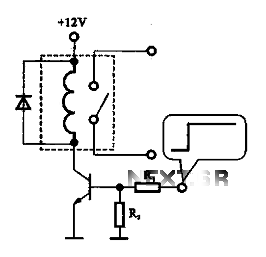
A relay control circuit is illustrated, which is commonly found in microwave switches. This circuit facilitates the operation of various components such as the power supply switch, electric fans, light bulbs, food turntables, and timers. The relay control signal...
The LM111 comparator can be utilized to design a relay driver with a TTL strobe, which enhances control over the relay driver. The strobe signal can be used to manage the relay operation more effectively. The LM111 is a high-speed...
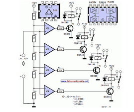
This circuit demonstrates that microprocessors, personal computers, and the latest ultra-accurate digital-to-analog converters (DACs) are excessive for the task of sequentially controlling four relays. The circuit utilizes a simple microcontroller or a basic timer IC to manage the operation of...
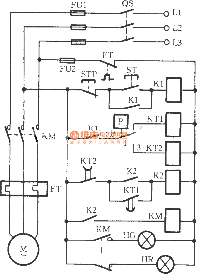
The circuit utilizes two time relays, KT1 and KT2, which are connected in series with the contacts of an electric contact pressure gauge (SP). This configuration helps to mitigate issues such as tremors or sparking that may occur due...