
Daylight alarm with 555

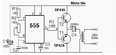
The described circuit utilizes a 555 timer IC configured in astable mode to generate a square wave output at approximately 1 kHz. This frequency is suitable for driving a speaker to produce a loud alarm sound. The light-dependent resistor (LDR) serves as a sensor that detects ambient light levels. In darkness, the resistance of the LDR is high, which keeps the base of the connected transistor in a non-conducting state. As a result, the transistor remains OFF, preventing current flow to the reset pin (pin 4) of the 555 timer, thereby keeping the timer in a reset state and stopping any oscillation.
When light is present, the resistance of the LDR decreases significantly, allowing current to flow to the base of the transistor. This action turns the transistor ON, effectively pulling the reset pin of the 555 timer high. Once the reset pin is activated, the 555 timer begins to oscillate, producing a square wave output. This output can drive a speaker, generating an audible alarm sound to wake the user.
The variable resistor, rated at 100K ohms, is crucial for adjusting the sensitivity of the circuit. By varying its resistance, the threshold light intensity required to trigger the alarm can be fine-tuned, allowing the circuit to function effectively in different lighting conditions. This adjustment capability ensures that the alarm can be set to activate only when desired, preventing false triggers from ambient light fluctuations.
Overall, this circuit is a practical application of the 555 timer and LDR technology, providing a simple yet effective solution for a light-activated alarm system.The circuit presented here wakes you up with a loud alarm at the break of the daylight. Once again the 555 timer is used here. It is working as an astable multivibrator at a frequency of about 1kHz. The circuit's operation can be explained as follows: When no light falls on the LDR, the transistor is pulled high by the variable resistor. Hence the transistor is OFF and the reset pin of the 555 is pulled low. Due the this the 555 is reset. When light falls on the LDR, its resistance decreases and pulls the base of the transistor low hence turning it ON. This pulls the reset pin 4 of the 555 high and hence enables the 555 oscillator and a sound is produced by the speaker.
The variable 100K resistor has to be adjusted to set the light intensity that triggers the alarm. 🔗 External reference
Related Circuits
The danger always exists when fuel gases such as propane or natural gas are confined to a small area. The toxic gas alarm utilizes a tin-oxide semiconductor. A coil of thin wire is heated by a 12 V battery...
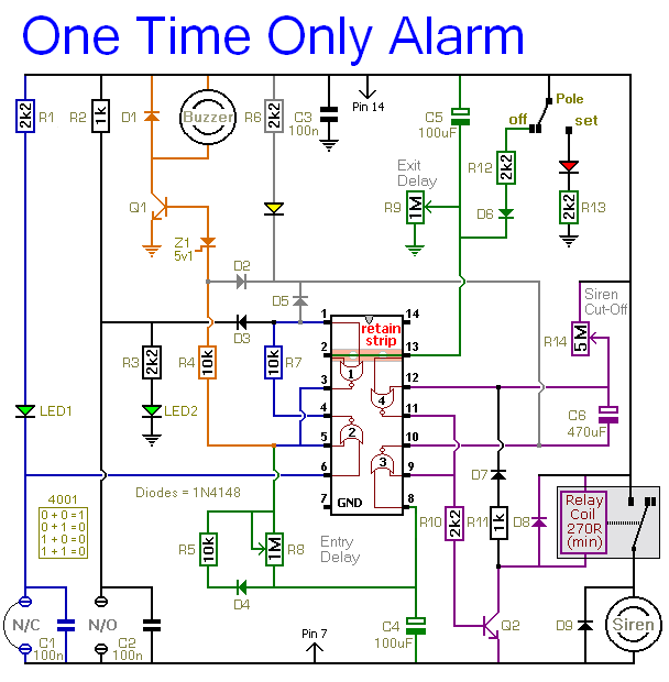
When this alarm is activated, its siren will sound once for up to 20 minutes. After this period, it will switch off and remain off. The basic circuit features a single zone with independently adjustable exit and entry delays,...
Beeper and/or LED remotely-operated via mains supply line. Pressing the pushbutton of the transmitter, a sound and/or light alert is activated in the receiver. The system uses no wiring or radio frequencies: the transmitted signal is conveyed into the...
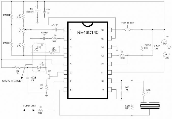
The RE46C140 circuit can be utilized to design a simple smoke detector alarm with minimal external electronic components. The RE46C140 integrated circuit (IC) is a low-power CMOS photoelectric smoke detector IC that encompasses all necessary features for a photoelectric...
This is a complete alarm system with five independent zones suitable for a small office or home environment. It utilizes three CMOS integrated circuits and features a timed entry/exit zone, four immediate zones, and a panic button. There are...
This 12V power inverter circuit can be utilized to supply power to small devices that require 240 volts. It is particularly beneficial when there is a need to operate equipment designed for 240 volts. The 12V power inverter circuit is...
Warning: include(partials/cookie-banner.php): Failed to open stream: Permission denied in /var/www/html/nextgr/view-circuit.php on line 713
Warning: include(): Failed opening 'partials/cookie-banner.php' for inclusion (include_path='.:/usr/share/php') in /var/www/html/nextgr/view-circuit.php on line 713