
DC Supply
The circuit operates as a linear voltage regulator, designed to provide a stable output voltage while ensuring safety through galvanic isolation. The isolation transformer is a critical component, as it separates the circuit from the main AC line, preventing any direct electrical connection that could pose a shock hazard during experiments with AC voltage.
The linear regulator functions by maintaining a constant output voltage, which is essential for powering sensitive electronic components or devices that require a specific voltage level. The use of an isolation transformer not only enhances safety but also improves the overall reliability of the circuit by filtering out high-frequency noise that may be present on the AC line.
The schematic typically includes input and output terminals clearly labeled for easy connection to the power source and the load, respectively. The input terminal connects to the primary side of the isolation transformer, while the output terminal connects to the load, ensuring that the load receives a stable and isolated voltage supply.
The circuit can be constructed on a universal PCB, allowing for flexibility in component placement and layout. This adaptability is beneficial for prototyping and testing various configurations. The output terminal is designed to handle significant loads, ensuring robust electrical contact and minimizing voltage drop across connections.
In summary, this linear regulator circuit with galvanic isolation is well-suited for experimental applications involving AC voltage, providing both safety and stability. The careful arrangement of components and the use of an isolation transformer make it an effective solution for powering various electronic projects.The circuit is a linear regulator providing galvanic isolation from main line through the use of isolation transformer. Quite safe for experimenting with AC voltage. Below pictures show the example of input/output terminal connections, labeling and components placement in the box.
The circuit can be built using universal PCB. The output terminal is for big load connection so this makes it quite strong and good electrical contact to the load being used. My workbench has many broken devices and most of them will be used as the part for making the electronic projects. One day I looked at the broken radio, I found there`s an AC line cord with socket and a transformer. Actually I like the way they used 🔗 External reference
Related Circuits
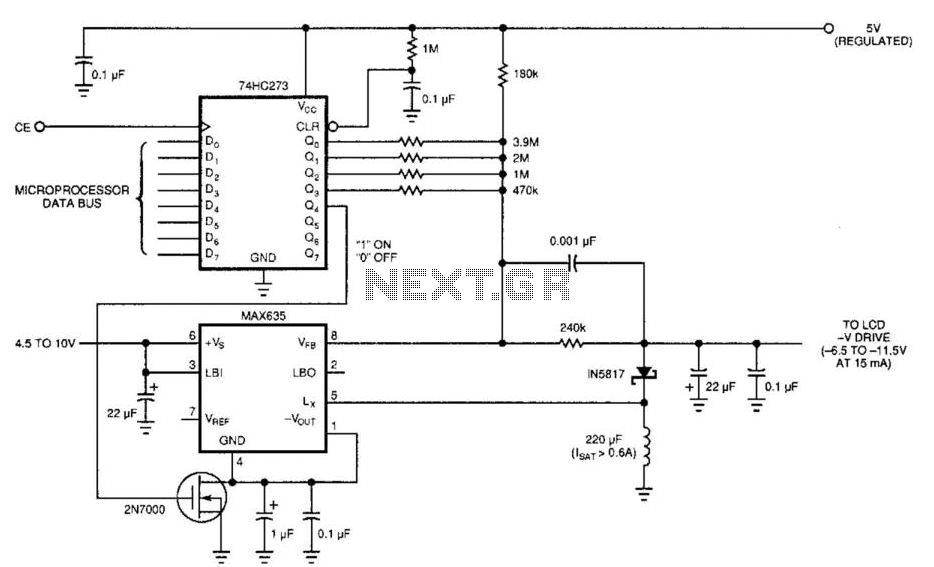
Laptop computers frequently utilize large-screen LCDs that require both a variable and a negative supply to achieve maximum contrast. This circuit operates from the system's positive battery supply and generates a digitally variable negative voltage to drive the display....
If a negative supply is required for an operational amplifier or if a negative bias voltage is needed while operating from a single supply voltage, such as in battery applications. To generate a negative supply voltage from a single positive...
This simple variable power supply circuit has a low production cost and delivers an output voltage between 1.5 V and 15 V with a maximum current of 500 mA. This variable power supply circuit is designed to provide a versatile...
The LM317 is an adjustable, positive 3-terminal voltage regulator capable of supplying 100 mA (for RA87U control) or 1.5 A (for Order Code UF27E and N61CA) across an output voltage range of 1.2 V to 37 V. These voltage...
The power supply is based on the LM317 and LM337 variable 3-terminal regulators ICs, and while it is no powerhouse, it is quite satisfactory for testing most power amps, as long as there is no speaker connected. The circuit utilizes...
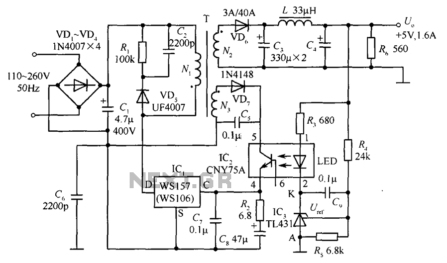
The circuit incorporates an optical coupler (CNY75A) and an adjustable precision shunt regulator (TL431). It includes current limiting resistors R3, R4, and R5 for the sampling resistor. As the output voltage (Uo) varies, the voltage across the sampling resistor...
Warning: include(partials/cookie-banner.php): Failed to open stream: Permission denied in /var/www/html/nextgr/view-circuit.php on line 713
Warning: include(): Failed opening 'partials/cookie-banner.php' for inclusion (include_path='.:/usr/share/php') in /var/www/html/nextgr/view-circuit.php on line 713