
dicing with leds
The electronic dice circuit utilizes a 4060 digital counter, which serves as the core component for generating random numbers corresponding to the dice faces. The circuit also incorporates a series of light-emitting diodes (LEDs) that represent the numbers 1 through 6. The user activates the circuit by pressing a button, which triggers the counting process within the 4060 IC.
The 4060 counter operates by counting pulses generated from an external clock source, which can be derived from an RC oscillator or another timing circuit. The output from the counter is configured to cycle through the states that correspond to the values displayed on the LEDs. Each state corresponds to a specific number on the die, and the LEDs light up accordingly to indicate the result of the roll.
To ensure that the dice remain fair and cannot be tampered with, the circuit may include additional features such as a reset mechanism that returns the counter to its initial state after a roll. This prevents the user from influencing the outcome by attempting to manipulate the circuit during operation.
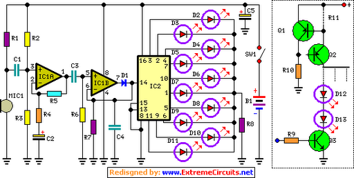
The compact nature of the design allows for easy integration into various DIY projects, making it a popular choice among hobbyists. The use of standard components also ensures that the circuit can be easily replicated and modified for different applications. Overall, this electronic dice project exemplifies the creativity and ingenuity of DIY electronics enthusiasts, offering a fun and interactive way to engage with basic circuit design principles.Every self-respecting DIYer makes his own electronic dice with LEDs as spots. Then you don t have to throw the dice anymore just push the button. The electronics also ensures that nobody can try to improve his luck by fiddling with the dice. Too bad for sore losers! This circuit proves that an electronic die built using standard components can be made quite compact. The key component of here is a type 4060 digital counter (IC1).. 🔗 External reference
Related Circuits
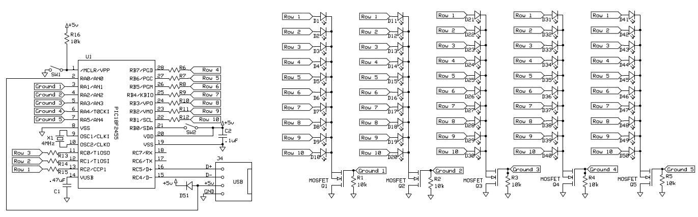
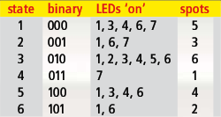
To control 40 LEDs using a single PIC 18F2455 microcontroller, the LEDs were organized into a configuration of four columns, each containing 10 rows of LEDs. Each LED in a column was connected to a separate pin on the...
This indicator shows through a dual-LED see if a fuse is intact. The module is designed for 230 V AC. The green LED illuminates when the fuse is still good, the red lights when the fuse is broken. Perhaps...

The basic circuit illuminates up to ten LEDs in sequence, synchronized with the rhythm of music or speech detected by a small microphone. The expanded version can drive up to ten strips, each consisting of up to five LEDs,...
The 555 timer IC is connected for Astable Operation, the clock pulses are fed to the 4017 IC via the 10K resistor. The 4017 is a 10 stage counter, therefore the sequence of the traffic lights is spread over...

This transistor has only one IC tester and can test all types of transistors. With two LEDs indicating the type of the transistor is NPN or PNP. The circuit uses a CMOS 4049 IC. The test transistor to terminals...
The basic circuit illuminates up to ten LEDs in sequence, following the rhythm of music or speech picked up by a small microphone. The expanded version can drive up to ten strips, each formed by up to five LEDs,...