
ds1820 interfacing with avr slicker
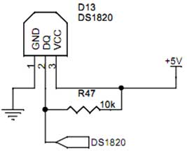
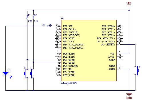
The DS1820 is a digital temperature sensor that communicates with microcontrollers through a single-wire interface. The connection involves three pins: the ground pin (first pin) provides a reference voltage, the VCC pin (third pin) supplies power, and the data pin (second pin) transmits temperature readings to the microcontroller. The AVR Slicker Board, equipped with an AVR microcontroller, utilizes PORTA for interfacing with the DS1820. The UART (Universal Asynchronous Receiver/Transmitter) is employed for serial communication, allowing temperature data to be sent to a PC for monitoring.
The CodeVision AVR software is essential for developing and debugging the application. It supports writing C code and includes a built-in compiler for AVR microcontrollers. Users must ensure that the software is properly installed, and a project is configured with the correct settings to compile the code effectively. The HEX file generated after compilation is necessary for programming the microcontroller.
The testing procedure involves powering the AVR Slicker Board with a +12V supply and establishing a serial connection to a PC. HyperTerminal is used to visualize the temperature data, where users can select the appropriate COM port and configure settings such as baud rate and data bits. The DS1820’s response to temperature changes can be tested by bringing a heat source, such as a soldering iron, close to its pins. This step demonstrates the sensor's capability to detect temperature variations accurately. If the temperature readings do not appear as expected, troubleshooting steps include verifying the serial cable connection and reviewing the code in debugging mode within the CodeVision AVR environment to ensure proper functionality.Interface the ds1820 to microcontroller. As you can see the first pin is connected to GND, the third pin is connected to VCC & the second pin is connected to the Microcontroller. So when the temperature is sensing, it give the sensor reading to controller. We now want to read the temperature in AVR Slicker Board from temperature sensor ds1820. AVR Slicker board uses the PORTA pin for reading temperature from temperature sensor ds1820. The reading output is displayed into PC through UART. To compile the above C code you need the CodeVision AVR software. The software has it`s own IDE and built-in AVR gcc- Compiler. They must be properly installed and a project with correct settings must be created in order to compile the code. To compile the above code, the C file must be added to the project. In CodeVision AVR software, you can develop or debug the project without any hardware setup. You must compile the code for generating HEX file. In debugging Mode, you want to check the port output without microcontroller Board. Give +12V power supply to AVR Slicker Board; the serial cable is connected between the controller and PC.
Open the Hyper Terminal screen, select which port you are using and set the default settings. Now the screen should show the current temperature readings. Bring a Hot soldering iron tip near the ds1820`s pins, don`t touch it keep it 1 or 2mm away. The screen should update with the rising temperature. Now finally touch the pins of ds1820 with the tip of iron, the temperature should rise quickly. Keep it there until temperature rise to 80 degrees, and then remove the iron. If any data is not coming in Hyper Terminal, then you just check the serial cable is working or not. Otherwise you just check the code with debugging mode in CodeVisionAVR. 🔗 External reference
Related Circuits

Usually we see Digital clock on LCD or 7 segment. But, this AVR Digital Clock which is designed by Ficara Emilio displayed on Oscilloscope. The project uses ATtiny 2313 as the main controller. What an interesting microcontroller project. Source...
A demonstration of external interrupts in the AVR (Atmega8) microcontroller, including a circuit diagram and C code for the interrupt service routine (ISR). The Atmega8 microcontroller is a versatile device widely used in embedded systems, particularly for applications requiring external...
A circuit diagram was created using KiCad, which is considered an excellent free software for designing electronic diagrams and printed circuit boards. KiCad is a powerful open-source software suite that allows engineers and hobbyists to design electronic circuits and...
The Arduino Uno features an ATMEGA328P-PU microcontroller and various additional components on the board. The objective is to program the microcontroller without relying on the Arduino software, utilizing only the essential components. The goal is to develop projects independently...
This article discusses the Gadgets, Gizmos, and Arduino (ATMega328). The content is straightforward and informative. The components mentioned in this article can enhance the understanding of the subject. For instance, readers can find and purchase components such as the...
You may find that there are too few, if your power is very noisy (as can happen in a car environment) it may help to place a 0.1uF and/or 10uF capacitor before and/or after the voltage regulator. At the...
Warning: include(partials/cookie-banner.php): Failed to open stream: Permission denied in /var/www/html/nextgr/view-circuit.php on line 713
Warning: include(): Failed opening 'partials/cookie-banner.php' for inclusion (include_path='.:/usr/share/php') in /var/www/html/nextgr/view-circuit.php on line 713