
Four reverse brake circuits to operate energy
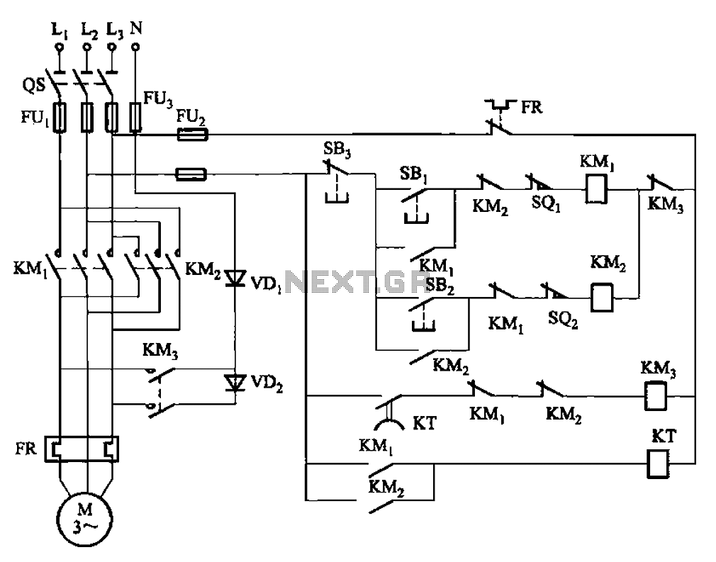
The circuit employs a time relay (KT) that plays a critical role in managing the braking process. By adjusting the relay's timing from 1 to 2 seconds, it can accommodate various operational conditions, ensuring that the braking action is neither too abrupt nor too prolonged. This adjustment is vital for applications where precision in stopping is necessary to prevent mechanical stress or damage to the system.
The forward and reverse operation terminal switches, SQ1 and SQ2, are integral to controlling the direction of motion in the system. These limit switches are activated when the mechanism reaches its respective end positions, ensuring that the motor does not exceed its designated operational range. This feature is crucial in automated systems where precise control of movement is required for safety and efficiency.
Incorporating these components into the circuit design enhances the overall reliability and performance of the braking system. The combination of the time relay and limit switches allows for a well-coordinated operation that minimizes the risk of mechanical failure and enhances user safety. The circuit's layout should be carefully designed to ensure that all connections are secure and that the relay and switches are positioned for optimal functionality within the broader system. Circuit shown in Figure 3-147. To allow sufficient braking time, using the time relay KT (1 ~ 2s, adjustable), the real on the occasion of a brake stop time may be short. Figur e, SQi, SQ2 respectively forward and reverse operation terminal (limit) switches.
Related Circuits
The following are LM555 timer circuits that have unusual functions. Designed to time a sports event; In this circuit the GREEN output is adjusted to be on for 3 minutes and then the RED output is set for 1...
The performance of the 80-meter CW transceiver using the phase method for sideband suppression is very good. Construction was easy with all standard electronic components available, without the need for an expensive or complex crystal filter. Almost no signals...
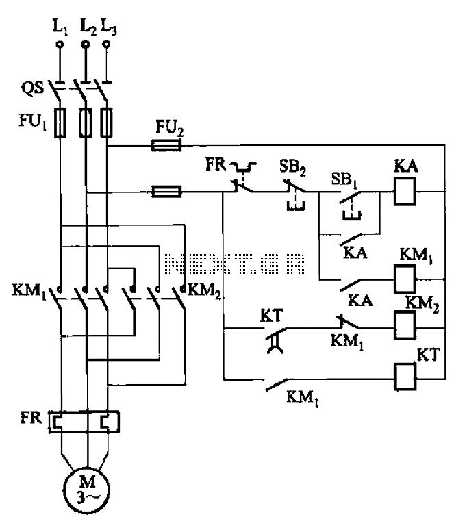
The circuit illustrated in Figure 3-127 utilizes a time relay (KT) in place of a speed relay. The timing duration is adjustable and typically set between 1 to 2 seconds. This circuit is designed to operate effectively in dusty...
This article compares high-side and low-side amplifiers used for measuring battery charging currents. It recommends selection criteria for current-sense resistors and describes a high-voltage circuit breaker designed for overcurrent protection. High-side and low-side amplifiers are essential components in battery management...
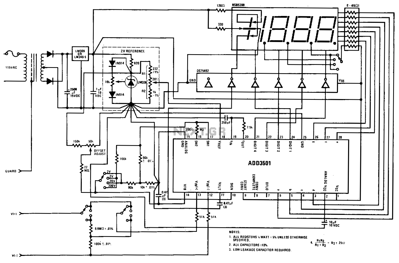
This digital voltmeter (DVM) circuit utilizes a National ADD3501 DVM chip along with an LM336 reference integrated circuit to construct a straightforward DVM with a minimal number of components. When designing a single-range panel meter, the components for range...
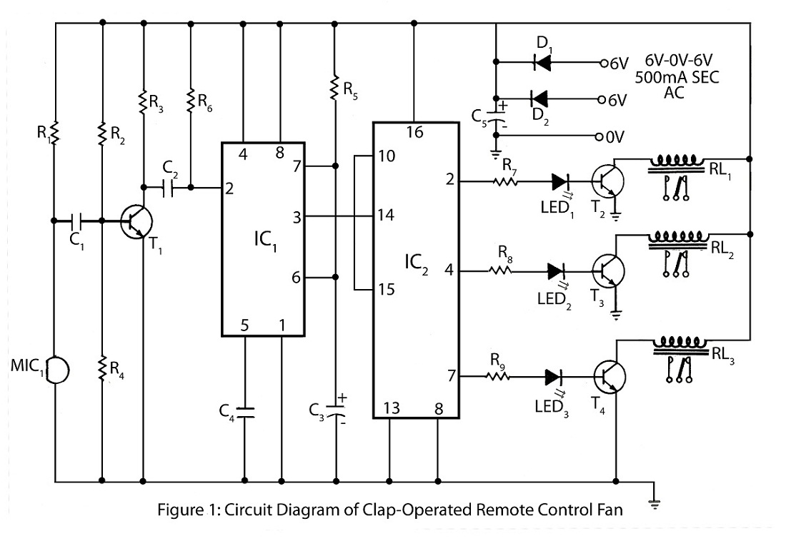
The clap-operated remote control for fans is designed to control a ten-step speed fan circuit. This includes a circuit diagram and a description of the clap-operated remote control system for fans. The clap-operated remote control system utilizes sound recognition to...