
Garage door open indicator
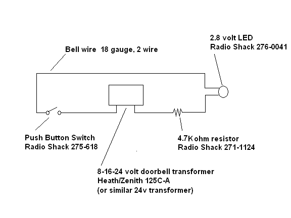
The proposed system involves a simple yet effective circuit design that utilizes a normally open momentary push button switch to indicate the status of a garage door. The switch is strategically mounted to engage when the door reaches its fully open position, ensuring that the circuit closes only at this critical point. The components include a 24-volt AC doorbell transformer, which steps down the voltage to a manageable level. The 4.7k-Ohm resistor is critical in this design, as it limits the current flowing to the LED indicator, preventing damage while allowing it to function correctly.
The installation process involves careful consideration of the mounting location for both the switch and the LED indicator to ensure discreetness and accessibility. The use of heat shrink tubing around the switch terminals enhances the durability and safety of the connections, protecting them from environmental factors. The wiring is routed in a manner that minimizes visibility and potential interference with other household activities, particularly in sensitive areas like the master bedroom.
This system serves as an effective reminder for the user, ensuring that the garage door's status is easily monitored without the need for intrusive electronic devices. The choice of components and the overall design reflect a balance between functionality and aesthetic considerations, making it a suitable addition to any home where maintaining the integrity of living spaces is a priority.There are battery powered wireless systems on the market, but the ones I found would signal that the door was open even if you left it open just a few inches for ventilation. I wanted a system that would alert me if we`d just plain forgotten that the door was in the fully raised position.
Also, if possible, I wanted the indicator to be as discreet as possible. We don`t need any more electronic gizmos sitting around the house and certainly not in the master bedroom, where my wife even objects to the (fairly small) ooma Scout on her night stand. I did find an article on a DIY system I`ll link to it a bit later in this post but the type of garage door in that article was different from mine.
The article did give me a wiring schematic that I could work from, so with that in mind I began inspecting my garage door for options for a switch of some sort. What I discovered was that the top edge of the door, when in the fully open position, was right near the angle iron that supports the rails for the door.
As a bonus, there was a bolt that I could mount a simple bracket from. So I headed to the local Radio Shack and bought $6 worth of components, stopped at the home center and picked up a doorbell transformer, 120 feet of two strand bell wire, and a couple of L or corner brackets, and was set. My total outlay was about $40. I started by reaming out a couple of the mounting holes on the larger of the two L brackets, installed a normally open/momentary on push button switch on the side facing the top of the door, and bolted the bracket to the angle iron support.
Here`s the installed switch, with the door stopped just short of being fully open: When the door is fully opened, the switch is depressed, closing the circuit. The bracket can be bent to ensure that the switch is fully depressed. Here`s the door fully opened, and the switch is closed: A bit later on, and the switch has been wired; I used some heat shrink tubing I had on hand to make sure everything around the switch terminals was sealed as well as could be: Next I wired the 24 volt transformer directly to a grounded plug and located it right above a power strip near my workbench.
The heat shrink tubing (directly beneath the transformer) covers a 4. 7k-Ohm resistor which was soldered in place: Before we go any further, here`s a simple wiring diagram for the system. The transformer I used was wired to produce 24 volts AC; the 4. 7k-Ohm resistor knocks the voltage down to the point where a 2. 8 volt LED can be used (you can click on this for a close-up): I ran the wire up the wall, across the ceiling, and into the attic.
Doing this on a day when the outside temp was about 80 °F did not turn out to be particularly brilliant, but once I had it in my head to do this, there was no turning back. I originally thought I`d just put the LED on the wall of the mud room, but then realized that if I`d remember to check the LED, I`d could just open the door of the mud room and look at the garage door itself.
No, I needed something foolproof, preferably something in the master closet or master bedroom. And I couldn`t get away with drilling a hole in the wall of the master for a red LED; if I did that, I`d be posting this from a hospital bed. She Who Must Be Obe 🔗 External reference
Related Circuits
This LED (Light Emitting Diode) display consists of 10 LEDs to indicate the level of an input signal. If the signal is low, only LED #1 will light up. As the signal level increases, the illuminated dot will progress...
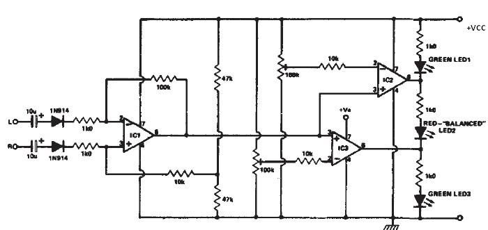
This stereo balance indicator circuit diagram is designed using a few common external components. The schematic circuit is very simple to build and will provide a visual indication with LEDs for left, right, and center balance. Outputs from each...
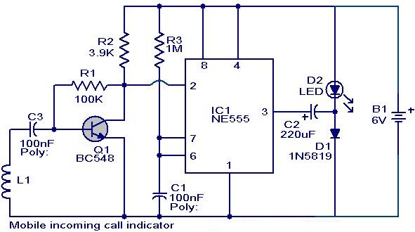
This circuit can be utilized to eliminate the annoyance of mobile phone rings while at home. It provides a visual indication when placed near a mobile phone, even if the ringer is turned off. When a call is received,...
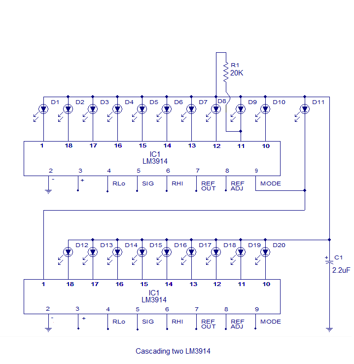
The core of this circuit is the LM3914 from National Semiconductor. The LM3914 is capable of sensing voltage levels and can drive a display of 10 LEDs in either dot mode or bar mode. The selection between bar mode...

The Arduino 2009 functions as an independent weather station without a display. It can operate autonomously for extended periods, sampling data from sensors until the RAM reaches full capacity. The collected data is stored in a designated sector of...
Modify it to click and latch a relay when the button is pressed from anywhere in the house. Additionally, if possible, unlatch the relay when pressed again. A flip-flop circuit may be created to take the first signal and...
Warning: include(partials/cookie-banner.php): Failed to open stream: Permission denied in /var/www/html/nextgr/view-circuit.php on line 713
Warning: include(): Failed opening 'partials/cookie-banner.php' for inclusion (include_path='.:/usr/share/php') in /var/www/html/nextgr/view-circuit.php on line 713