
High Impedance DC Voltmeter using MOS Op-Amp
The high-impedance voltmeter circuit typically employs operational amplifiers (op-amps) configured in a non-inverting arrangement to ensure minimal loading on the circuit under test. This configuration is essential for accurately measuring the voltage without significantly affecting the circuit's operation.
The input stage of the voltmeter consists of a precision op-amp, which is chosen for its high input impedance, usually in the range of megaohms, and low offset voltage to enhance measurement accuracy. The op-amp's non-inverting input receives the voltage to be measured, while the inverting input is connected to a feedback resistor network that sets the gain of the amplifier.
To convert the output voltage of the op-amp to a readable format, a digital voltmeter (DVM) or an analog display can be used. If a DVM is employed, an Analog-to-Digital Converter (ADC) may be integrated into the circuit, allowing for digital readouts of the measured voltage. The circuit may also include a reference voltage source to calibrate the measurement range, ensuring that the displayed voltage accurately corresponds to the input voltage.
Additional components in the circuit may include protection diodes to prevent damage from overvoltage conditions, as well as filtering capacitors to minimize noise and stabilize the readings. The layout of the circuit should be carefully considered to reduce interference and ensure accurate measurements, particularly in environments with fluctuating electrical noise.
Overall, this high-impedance voltmeter design is suitable for applications where precise voltage measurements are required without impacting the performance of the circuit being tested.The circuit was designed for the purpose of creating a voltmeter with high impedance that would measure Direct Current voltages across any types of circui. 🔗 External reference
Related Circuits
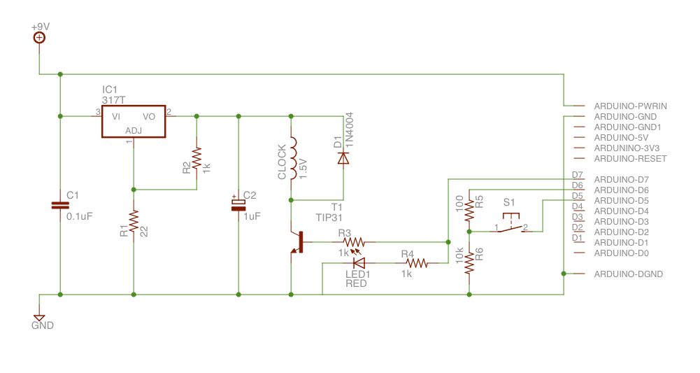
The output of the transformer has been calculated to be 125 times higher than the input, based on the ratio of 1000 to 8. Given an input of 12V, the expected output should be 1500V, although there is some...
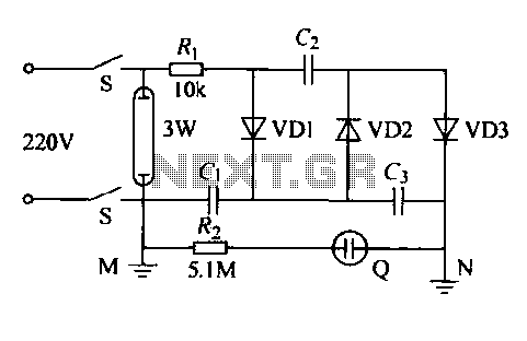
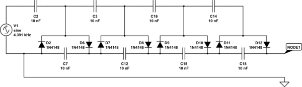
The IED functions as a hotel, restaurant, and family-oriented tool designed for the effective eradication of mosquitoes, as illustrated in Figure 16-12a. It employs a diode voltage doubler rectifier circuit to generate a high voltage. When mosquitoes are attracted...
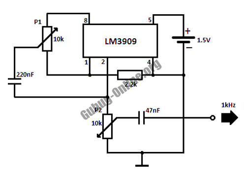
This circuit design for a high-frequency waveform generator is highly beneficial for electronic experiments and designs. The circuit generates sine wave oscillations, but it can also be modified to produce triangle or square wave functions. The high-frequency waveform generator circuit...
Upon purchasing the slave dial, it arrived without instructions, packaging, or additional details. The only visible markings, aside from decades of grime, were on the face (SMITH SECTRIC, ACELEC SYDNEY) and some markings on the bracket holding the mechanism...
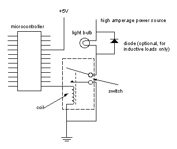
Digital output from a microcontroller is typically a low-amperage signal. For example, when a pin is set HIGH on the microcontroller (in Wiring/Arduino, it is digitalWrite(somePin, HIGH);), the voltage from that pin is usually +3.3V or +5V, with the...
The losses in a bridge rectifier can become significant when low voltages are being rectified. The voltage drop across the bridge is approximately 1.5 V, which represents about 25% of an input voltage of 6V. The loss can be...