
Infra Red Remote Control Extender
The described circuit provides a low-cost solution for controlling a satellite receiver or similar device remotely using a wired connection. The primary components of this circuit include a transmitter unit that connects to the remote control and a receiver unit that interfaces with the satellite receiver.
The transmitter unit typically consists of a microcontroller or a simple logic circuit that interprets the signals from the remote control. It converts these signals into a format suitable for transmission over a cable. The circuit may include a small infrared (IR) LED or a similar device to emit the control signals, which can be directed toward the satellite receiver.
The receiver unit is designed to capture the signals sent from the transmitter. It usually contains a photodiode or phototransistor that detects the emitted signals and converts them back into electrical signals. These signals are then processed by another microcontroller or logic circuit that replicates the function of the original remote control.
The connection between the transmitter and receiver can be accomplished using a standard audio or video cable, which helps in maintaining a reliable and interference-free communication link. This wired approach eliminates the need for radio frequency transmission, which can be subject to interference and range limitations.
To implement this circuit effectively, it is essential to ensure that the wiring is appropriately shielded and that the components are positioned to avoid any potential signal loss. Additionally, careful consideration should be given to the power supply requirements of both the transmitter and receiver units to ensure consistent operation.
Overall, this circuit represents a cost-effective alternative to commercially available wireless remote control systems, providing users with the ability to control their devices without the significant expense associated with wireless technology.I have seen these devices advertised in magazines, they sell for around £40-£50 and use radio to transmit between receiver and transmitter. This version costs under £5 to make and uses a cable connection between receiver and transmitter. For example, if you have a bedroom TV set that is wired to the video or satellite in another room, then you can change channels on the remote satellite receiver using this circuit.
🔗 External reference
Related Circuits
The laser-pointer detection circuitry is capable of identifying when a laser light is directed at a specific photosensor. If the laser targets the top sensor, the comparator chip outputs a high signal. Conversely, if the laser is aimed at...
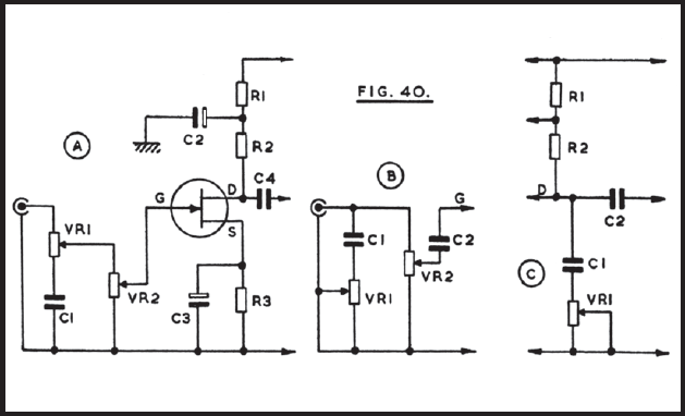
The circuit operates from a 12V or similar power supply, with the option to adjust resistor R1 for higher voltage applications. There is significant flexibility in selecting values for components like capacitor C1. At point B, VR1 serves as...
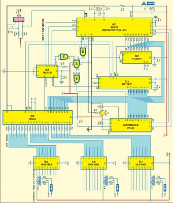
This project is based on the Atmel AT89C52 microcontroller and the Dallas real-time clock (RTC) chip DS12887. It can control and remotely program the switching operations of 24 electrically operated devices, allowing them to be turned on or off...
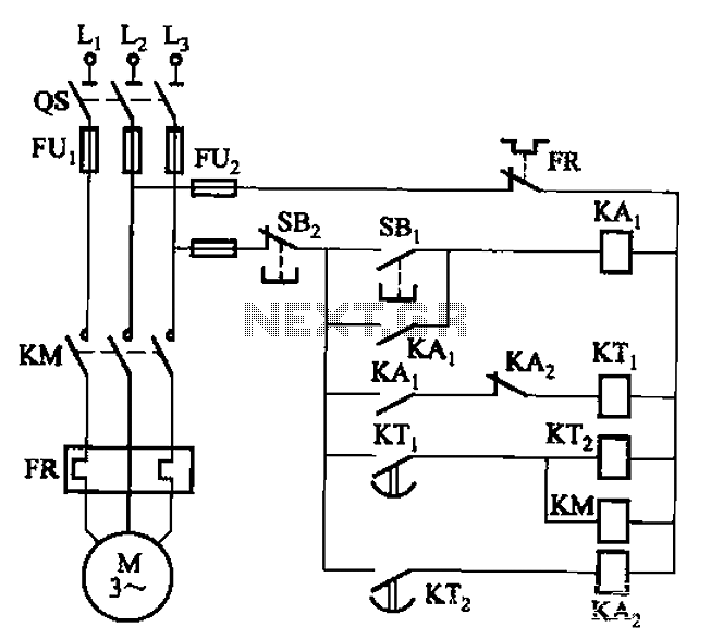
The circuit illustrated in Figure 3-76 employs two time relays, KTi and KTz, to manage the operation and downtime of a motor. The circuit utilizes two time relays to provide precise control over the motor's operational cycles. Relay KTi is...
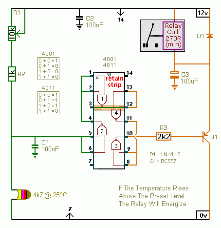
The first circuit energizes the relay when the temperature rises above the preset level. The second circuit energizes the relay when the temperature falls below the preset level. The two circuits are practically identical. The only difference between them...
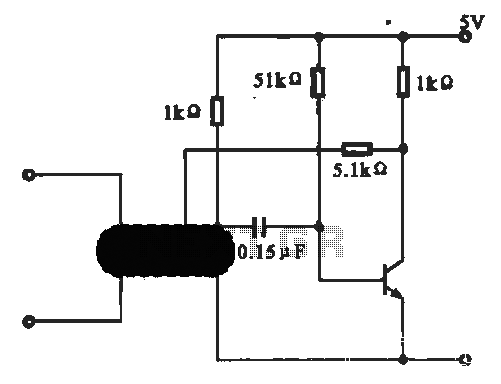
This circuit illustrates an oscillator that is controlled by an optocoupler, utilizing photoelectric coupling to drive a transistor. The oscillator circuit described operates by employing an optocoupler to provide electrical isolation between its input and output stages while allowing control...
Warning: include(partials/cookie-banner.php): Failed to open stream: Permission denied in /var/www/html/nextgr/view-circuit.php on line 713
Warning: include(): Failed opening 'partials/cookie-banner.php' for inclusion (include_path='.:/usr/share/php') in /var/www/html/nextgr/view-circuit.php on line 713