
interfacing large load bank with
The output port expander circuit for the 8051 microcontroller is designed to manage a large number of solid-state relays, which are essential in applications requiring the control of high power loads. The use of shift registers, specifically the 74LS4094 or the CD4094, allows for the expansion of the output capabilities of the microcontroller, enabling it to control up to 50 relays with minimal complexity in the circuit design.
The circuit operates by utilizing the serial input from the microcontroller, which is then converted into parallel output signals through the shift register. This approach significantly reduces the number of microcontroller pins required for direct relay control, simplifying the overall design. Each relay can be individually controlled by sending specific commands over an RS232 serial connection, allowing for flexible and dynamic control of the load bank.
The load bank itself can be configured to switch high voltages and currents, making it suitable for various industrial applications. The relays function as switches, enabling or disabling power to connected loads based on the commands received from the microcontroller. This setup is particularly beneficial in scenarios where multiple loads need to be controlled simultaneously or in a sequential manner.
In addition to the primary functionality, the project can serve as an educational tool for students and professionals looking to understand the principles of interfacing microcontrollers with external devices. It provides practical experience in working with shift registers, serial communication, and relay control, which are fundamental concepts in the field of electronics and embedded systems.This project is output port expander of microcontroller 8051. In this project we will learn, how to interface a large load bank with microcontroller 8051. In this load bank project, up to 50 solid state relays are interfaced with microcontroller using shift register 74LS4094 TTL IC, student can use CD4094 CMOS IC, any of them will work here fine. The basic purpose of this microcontroller project is to learn the interfacing of shift register for output port expansion. This project is for bank load which could be in the form of a large number of relays to switch ON or OFF the high voltages and high current loads.
The same project can be used for the interfacing of solid state relays. This is improved version of last project ( Control solid state relays up to 50 with microcontroller 8051 ) in which latches were used. The wiring diagram of that project was complicated. Thus by using serial to parallel shift register ICs, the circuit diagram is quit simple now. To turn ON any individual LED for load, command is n01 or N01 from RS232 serial communication from PC, you can use hyper terminal for testing the project or you can write your own code in any PC language.
relay switch atmel microcontroller51, interfacing relays with 8051, PLC output on relay switch, how a relay is behave like a switch, load bank consisting of many relays, bank load of relays and switches, data flow diagram of modem data rate analysis, industrial electronics circuit diagram 🔗 External reference
Related Circuits
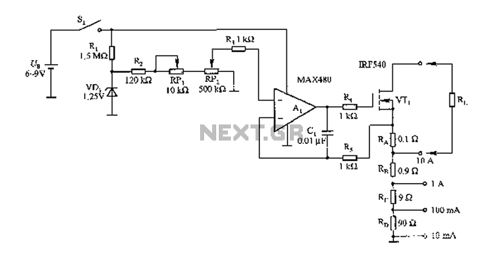
The FIG load test is a control circuit designed for external loads up to 10A, commonly utilized in drive test power applications, power amplifiers, LED solenoids, and relays. It is capable of handling various resistive loads and features a...
The NI 655X is a versatile high-speed digital product capable of interfacing with various technologies. This application note illustrates how to connect the NI 655X to Low Voltage Differential Signaling (LVDS) devices. LVDS is an emerging differential digital standard...
The TMS320C5505 Evaluation Board is specifically designed for developers in the DSP field as well as for beginners. The kit is structured in such a way that all possible features of the DSP can be easily utilized by everyone....
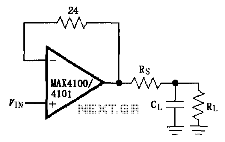
The MAX4100/4101 operational amplifiers utilize a capacitive load drive circuit with an isolation resistor Rs. The MAX4100 and MAX4101 can handle maximum capacitive loads of 5pF and 20pF, respectively, but are susceptible to overshoot and ringing oscillations. To mitigate...
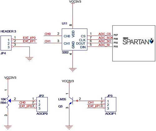
The Spartan-6 board features a 2-channel, 12-bit SPI ADC, as shown in the accompanying figure. In synchronous serial communication, a clock line (SCK in the case of SPI) is used to synchronize data transfer, with the clock being controlled...
As circuit power supply voltages decrease and green energy trends gain popularity, designers should re-evaluate circuits that continuously consume power to reduce overall system power consumption. One such circuit is the "normally-ON" circuit, which can now be redesigned with...
Warning: include(partials/cookie-banner.php): Failed to open stream: Permission denied in /var/www/html/nextgr/view-circuit.php on line 713
Warning: include(): Failed opening 'partials/cookie-banner.php' for inclusion (include_path='.:/usr/share/php') in /var/www/html/nextgr/view-circuit.php on line 713