
iPod FM Transmitter
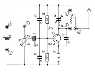
The iPod FM transmitter circuit is designed to operate within a specified frequency range, allowing users to broadcast audio wirelessly to FM radios. The circuit begins with the power supply, which is a 9V battery providing the necessary voltage for operation. The transistor (2N2219A) serves as the main amplifying component, enabling the modulation of the input audio signal.
The input audio is fed into the circuit at point c and is coupled through a resistor (R5) that functions as a trimmer to adjust the input signal level. This adjustment is crucial for ensuring that the audio signal is neither too weak nor too strong, which could lead to distortion or poor transmission quality.
Capacitor C6 is a trimmer capacitor that allows for fine-tuning of the transmitter’s output frequency. By adjusting this component, users can ensure that the transmitter operates on a frequency that is not occupied by other radio stations, thereby minimizing interference.
The antenna, constructed from a 70 cm copper wire, plays a critical role in radiating the modulated signal. The design specifies a spool (L1) made from silver wire, which acts as an inductor, enhancing the transmitter's performance. The specified dimensions ensure that the antenna and inductor are optimized for the desired transmission range of 100 to 150 meters.
Overall, this FM transmitter design is an effective project for individuals interested in exploring radio frequency transmission and audio broadcasting, combining basic electronic components to create a functional and practical device. Proper assembly and tuning of the components will yield a reliable transmitter capable of delivering clear audio over the specified distance.Building your own ipod FM radio transmitter. It works quite easy, there is a power switch on the bottom to turn it on and tune your radio and transmitter to the right frequency. For the antenna you can use a copper wire of 70 cm. The range of this FM transmitter is about 100 to 150 meters (500 feet). With R5 you can adjus t the input signal and with C6 you can tune your frequency. Transmitter is supplied by 9V battery. iPod FM Transmitter parts list: Transistor: T3. 2N2219a Capacitor: C3. 1 F/16 V C4, C5. 1 nF ker. C6 trimmer capacitor. 4-40 pF C7. 10 pF ker. Resistor: R5 Trimmer. 10 k © R6. 10 k © R7. 2, 7 k © R8. 1 k © Spool L1: Use a 10 cm long Silver wire. The diameter inside the spool should be 3 mm. 7 winds total Length of the spool should be 15 mm (f-g) The antenna is connected to the spool at 3mm from f a: + 9volt b: ground c: audio in Ground your audio input to b For the antenna you can use a copper wire (70 cm) With R5 you can adjust the input signal and with C6 you can tune your frequency. 🔗 External reference
Related Circuits
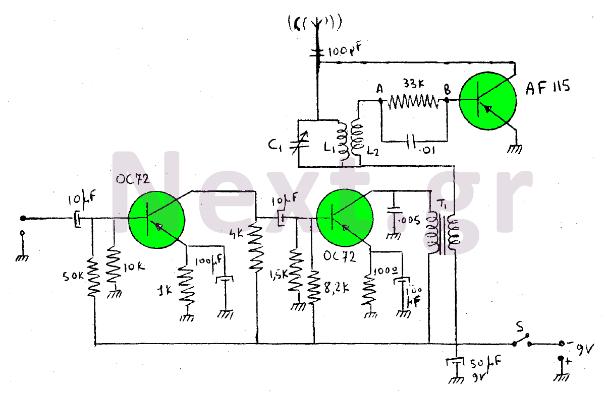
This device is a transmitter operating on medium-wave and short-wave frequencies, utilizing three transistors. The AF115 transistor serves as the oscillator within the circuit. The low-frequency amplifier, consisting of two OC72 transistors, functions as the modulator that generates the...
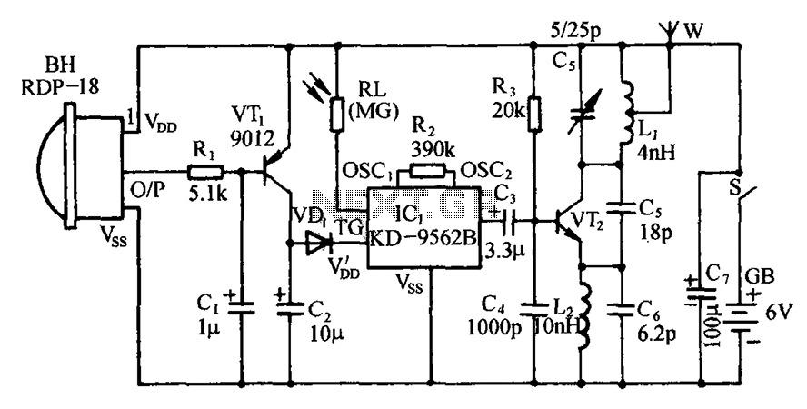
The circuit includes an infrared sensor head, electronic switches, an audible audio circuit, and an FM radio circuit. It is designed for installation in banks, treasuries, and other areas requiring supervision during evening hours in lieu of staff presence....
This is a low-cost and easy-to-build low-powered FM transmitter. The range of the FM transmitter is claimed to be about 300 feet when operating at a 9V supply. The range is said to increase to approximately 400 feet when...
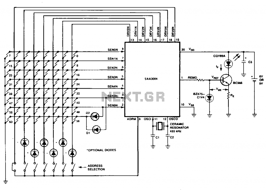
The transmitter keyboard is organized as a scanned matrix consisting of 7 driver outputs and 7 sense inputs. The driver outputs, labeled DRVON to DRV6N, are open-drain n-channel transistors that remain conductive in standby mode. The 7 sense inputs,...
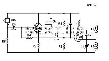
This circuit is designed for low power operation and can be tuned to function within the frequency range of 87-108 MHz, achieving a transmission distance of 20 to 30 meters. The circuit utilizes a pair of BC548 transistors, which,...

This is a mini FM transmitter powered by two transistors and designed by Tony van Roon. This compact transmitter is straightforward to assemble, and its signals can be received on any standard FM radio. It has a range of...