
Joulethief SEC exciter and variants 64
The Slayer exciter circuit described operates on the principle of resonant inductive coupling, where the energy from the primary coil is transferred to the secondary coil through magnetic fields. The primary coil, with its specified turns and wire gauge, serves as the initial inductor, while the secondary coil, configured with a higher number of turns, is designed to step up the voltage. The use of a C1815 transistor allows for efficient switching, enabling the circuit to oscillate and generate the high-frequency signals needed for effective energy transfer.
The integration of a variable potentiometer provides adjustable control over the brightness of the LED, allowing for real-time feedback on the circuit's performance. The inclusion of a 1N4148 diode instead of a traditional LED further optimizes the circuit's compactness, making it suitable for applications where space is a constraint. The Zener diode suggestion introduces an additional layer of functionality, as it can help regulate voltage levels within the circuit, ensuring safe operation and preventing damage to components.
The coil configurations, with their specific turns and wire diameters, are critical in achieving the desired resonant frequency and maximizing energy transfer efficiency. The challenge of achieving self-oscillation is a common hurdle in similar circuits, often requiring fine-tuning of component values and circuit layout. The proposed use of a Joule Thief circuit indicates a focus on low-voltage operation, which is beneficial for battery-powered applications, enhancing the practicality of the design.
Documentation of the build process and operational theory is essential for knowledge dissemination within the maker community. By sharing insights and experiences, builders can contribute to a collective understanding of Slayer exciters and similar technologies, fostering innovation and exploration in this niche field. The potential for creating a comprehensive guide on platforms like Instructables could serve to inspire a new generation of enthusiasts interested in Tesla-inspired technologies.After some more time with the circuit, the variable pot certainly brings in more useful results than I expected. Had linked draw to pot position and LED brightness, but not to transistor on-time. It should be obvious and now is, after reading your p ost. @Lightning - if still looking for solutions, i`d say check out Zener diodes. I don`t understand all about them myself, but they will break down at many different voltages depending on type and then might trip an `Off` circuit at that voltage. It`s wound with approx 600 turns of 30 gauge wire from Mabuchi RF-300 motors/printout calculator solenoids/PC floppy drive coils or maybe even folks buy such wire new lol.
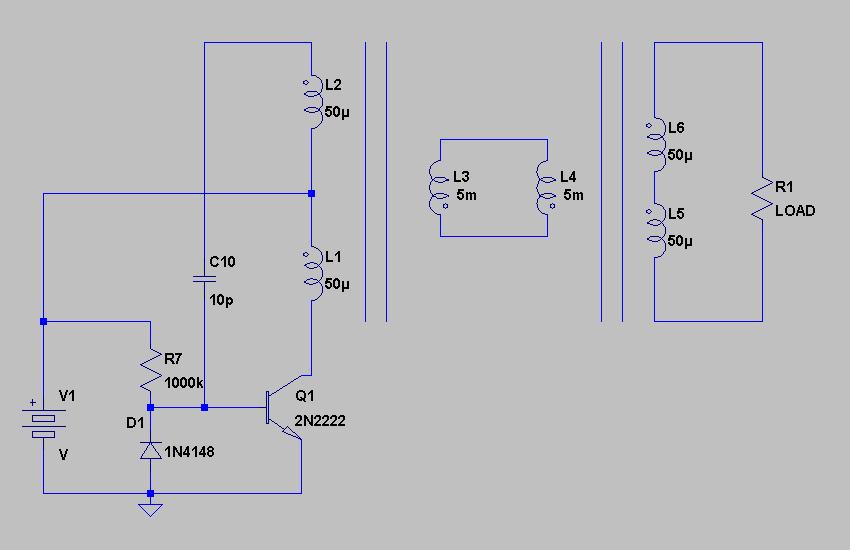
Circuit is a physically condensed Slayer exciter, using a standard and very normal C1815 as transistor, nothing fancy. The normal LED for a transistor is replaced with a 1N4148 diode, to further reduce size. The circuit for the LED is from one of Lidmotor`s circuits, the sMartCreations one you may have seen on his YouTube channel from March, that powers a pulse motor.
ya know ive ben meaning to ask, would it be alright if i made an instructables page detailing the build and basic operation of a slayer exciter, i found that there are few mainstream sites that have any info about this sort of tech. quite sad really. and there are a large amount of builders out there who enjoy playing with tesla sort of stuff. and a bigger following could mean more advances in it. i don`t know the last time slayer looked at this thread but i think idt be worth it if he at least thought about it.
ya know ive ben meaning to ask, would it be alright if i made an instructables page detailing the build and basic operation of a slayer exciter, i found that there are few mainstream sites that have any info about this sort of tech. quite sad really. and there are a large amount of builders out there who enjoy playing with tesla sort of stuff. and a bigger following could mean more advances in it. i don`t know the last time slayer looked at this thread but i think idt be worth it if he at least thought about it.
alright well thanks for the permission, i look forward to starting it at my earliest convenience, need to order some parts to do a nice build. if you didn`t see my last build was a mini with the ferrite core, high gauge wire (relatively) and an incorrect transistor.
so anyway i hope to do and document a very high quality build, might be awahile though, going to visit family in the midwest for a good 3 weeks, no sense ordering parts to there cause then i wouldn`t have the means to get it back. (would be funny explaining to tsa what an exciter is) its gonna be hard making this as an intractable, its not like this is overly well understood stuff, im hoping i can get input from everyone so that explaining the theory of operation (hazards, suggested uses, ect) won`t be so.
painful. The coil has got a 9 and 3/4 turn x 1mm primary, the cone is 156 turns 0. 5mm and the cylinder is 800 turns 0. 2mm The cone and the cylinder tower are joined of course. I can`t seem to get it to oscillate but I always have trouble with self oscillating circuits. Do any of you guy`s think this could work I`m also short of solderless board space so I don`t want to clear an exsisting circuit just yet. I want to use a JT circuit to drive the primary of the small coil in my previous post. And I want it to work from between 3v to 6v or maybe 12v if it worked from 1. 5 volts then even better. When I look at your circuit, you have an oscillator very similar to what I have drawn some time ago, with the idea of getting to identical (aircore ) transformers into resonance, just as you resonate one large coil with the JT circuit, so you get a signal on the second transformer that should be low voltage but able to give relatively large amperage, so you may be able to add a diode bridge as load and close the loop eventually.
(The coil values shown are just to indicate wh 🔗 External reference
Related Circuits
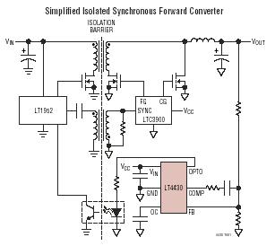
The LT4430 drives the opto-coupler that crosses the galvanic barrier in an isolated power supply. The IC contains a precision-trimmed reference, a high bandwidth error amplifier, an inverting gain of 6 stage to drive the opto-coupler, and unique overshoot...
The circuit is a 0-60 second timer using timer 555 and two 4017 for LED driving. The described circuit employs a 555 timer IC configured in monostable mode to create a timing interval ranging from 0 to 60 seconds. The...
The SB0061 is a pyroelectric sensor module designed for human body detection. It integrates a PIR (Passive Infrared) detector with a Fresnel lens on a compact printed circuit board (PCB), along with an analog integrated circuit (IC) identified as...

These are notes on teaching mini-classes in the science or engineering fields. In the context of educational methodologies for science and engineering disciplines, mini-classes serve as an effective instructional strategy. These classes typically involve condensed learning sessions focused on specific...
Ethernet is the most widely used networking technology, known for its high reliability, informative media, and ease of expansion and updates. It is commonly utilized in businesses, schools, and various other fields. According to the IEEE802.3 Ethernet specification, the...
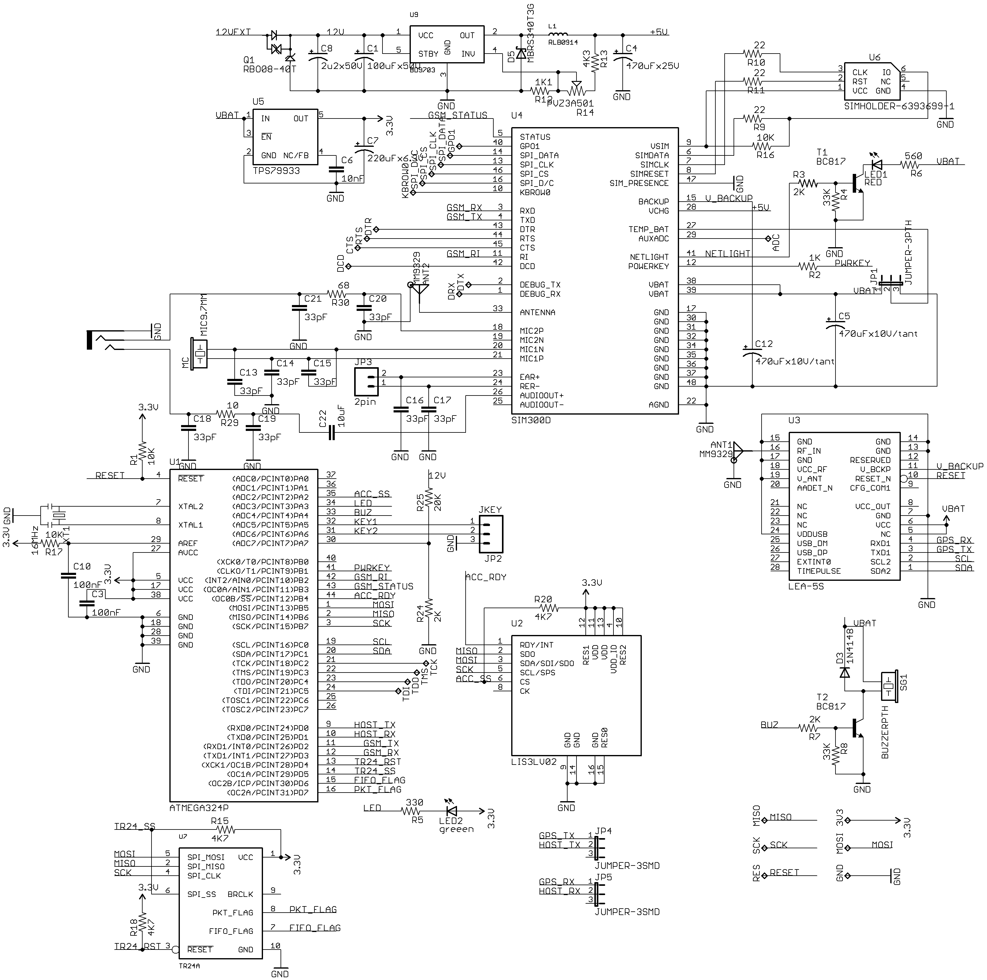
New uTracker on GE865 with a compact design. This updated version of the tracker features the SIM300DZ and EB-230/LEA-5S modules. It includes an OBD-II (ISO) sensor, an accelerometer, and an RFID reader. Additionally, a TR24 2.4GHz module is incorporated,...
Warning: include(partials/cookie-banner.php): Failed to open stream: Permission denied in /var/www/html/nextgr/view-circuit.php on line 713
Warning: include(): Failed opening 'partials/cookie-banner.php' for inclusion (include_path='.:/usr/share/php') in /var/www/html/nextgr/view-circuit.php on line 713