
LCD to a PC Parallel Port
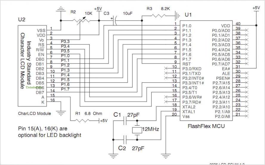
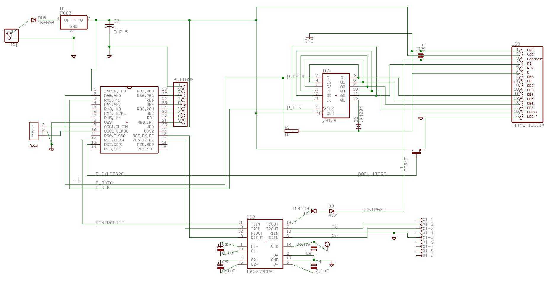
The circuit described integrates an LCD module with a parallel port interface, utilizing the data lines of the parallel port to communicate with the LCD. The connections between the LCD and the parallel port are straightforward, with data lines directly matched. Additional I/O lines from the parallel port are repurposed to simulate the control signals required by the LCD, specifically the RS (Register Select), R/W (Read/Write), and E (Enable) signals.
The LCD module's power requirements are minimal, allowing it to be powered directly from the parallel port in most desktop configurations. However, it is noted that certain laptops may not provide sufficient current to power the LCD adequately. A 10K potentiometer is included in the design to adjust the contrast of the display. Although it is recommended for flexibility, practical experience suggests that the potentiometer often ends up being set to ground, indicating that a direct connection to ground for the contrast pin (VLC) may suffice in many applications.
To protect the parallel port from potential backflow of voltage, a diode is connected from pin 17 of the printer port to pin 2 of the LCD. This diode serves as a safeguard in scenarios where an external power supply is used. In cases where an external supply is utilized, it should be connected to the designated "+5V" point on the schematic. This external power source can also be employed to drive the LCD's backlight, which requires a current-limiting resistor. It is suggested that a resistor value of 100 ohms, while possibly too high, will still allow the backlight to function, albeit at a reduced brightness.
The physical assembly of the circuit is accomplished using a protoboard, with a DB25 connector for the printer port and a 16-pin terminal strip for the LCD connections. The interconnects are managed on the reverse side of the protoboard, resulting in a functional, albeit not aesthetically refined, implementation.The circuit is pretty simple. The data lines on the LCD match up well with the data lines of the parallel port, and extra parallel port I/O lines can be used to simulate the RS, R/W, and E signals on the LCD. The LCD module is pretty low-lower (with the exception of the backlight), so I found that it can be powered from most parallel ports.
It worked fine with all the desktop PC's I tried it with, but a laptop I tried (a Toshiba something-or-other) just didn't have enough oomph to power the LCD The 10K pot controls the contrast of the LCD, though, in practice, I've found that it usually ends up at the ground rail, so you might be able to get by without the pot, and just tie VLC to ground. The diode from pin 17 of the printer port to pin 2 of the LCD simply blocks voltage from flowing back into the printer port (in case you hook up an external power supply).
If you use an external supply, it's intended to connect to the place on the schematic labeled "+5V". This external supply can also be used to power the LCD's LED backlight (through a current-limiting resistor -- 100 ohms is probably too high, but it will turn the backlight on at least dimly). I built this circuit up on a little Radio Shack protoboard, using a DB25 for the printer port connector, and a 16-pin terminal strip for the LCD connector, with the interconnects on the back.
Not pretty, but it works fine ... 🔗 External reference
Related Circuits
Spectrum-analyzer project 2007 update. Since the development of the wide-band VCO almost 10 years ago, the entire spectrum-analyzer project has progressed significantly. The spectrum analyzer project initiated in 2007 focuses on the development and enhancement of a wide-band Voltage Controlled...
High-precision voltage regulator, isolation transformer with the correct wiring, and low-pass filter to enhance the electrical noise immunity of the source portion. The wiring in Figures 20-48 and 20-49 is illustrated in the figures. Chokes (L1, L2) should have...
The FM497 is an integrated electronic ignition controller designed for breakerless ignition systems that utilize Hall effect sensors. This device operates an external NPN Darlington transistor to manage the coil current, thereby delivering the necessary stored energy while maintaining...
INTRODUCTION It is essential to monitor the operation of nearly all automated and semi-automated devices, such as washing machines and autonomous systems. Monitoring the functionality of automated and semi-automated devices is crucial for ensuring optimal performance and reliability. This can...
There is enough of poorly constructed RS232 alike TTL level interfaces (+5volt), this one generates its own +/- 10..11 volts as RS232 specs require, and is able to use very long cables like RS232 can, and protects computer as...
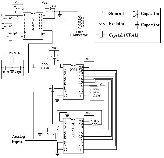
Data Collection - Analog to Digital Conversion and Communicating with a PC through the Serial Port Microcontroller Advanced Kit. The system described involves the process of data collection through analog-to-digital conversion, enabling communication with a personal computer via a serial...