
LEDs and Switches
The DE2 board is designed to facilitate various input and output operations through its integrated components. The four debounced pushbutton switches utilize Schmitt Trigger circuits to provide stable and reliable transitions between logic levels, mitigating the effects of mechanical bounce that can occur during switch actuation. This feature enhances the performance of the switches when used for critical functions such as clock signals or reset inputs in digital circuits.
The connection of the switches to the Cyclone II FPGA allows for seamless integration into digital designs, enabling the FPGA to read the status of each switch accurately. The toggle switches, while lacking debouncing, serve as effective level-sensitive inputs, providing a straightforward method for users to interact with the FPGA. The clear logic level outputs from the toggle switches make them suitable for applications where continuous monitoring of the switch state is necessary.
The presence of 27 user-controllable LEDs offers visual feedback for the operation of the circuit. The arrangement of red and green LEDs allows for differentiated signaling, where red LEDs can indicate specific states or statuses of the toggle switches, while green LEDs can provide feedback from the pushbutton switches. The direct connection of the LEDs to the Cyclone II FPGA ensures that the control over these indicators is straightforward and flexible, allowing for dynamic updates based on the logic implemented within the FPGA.
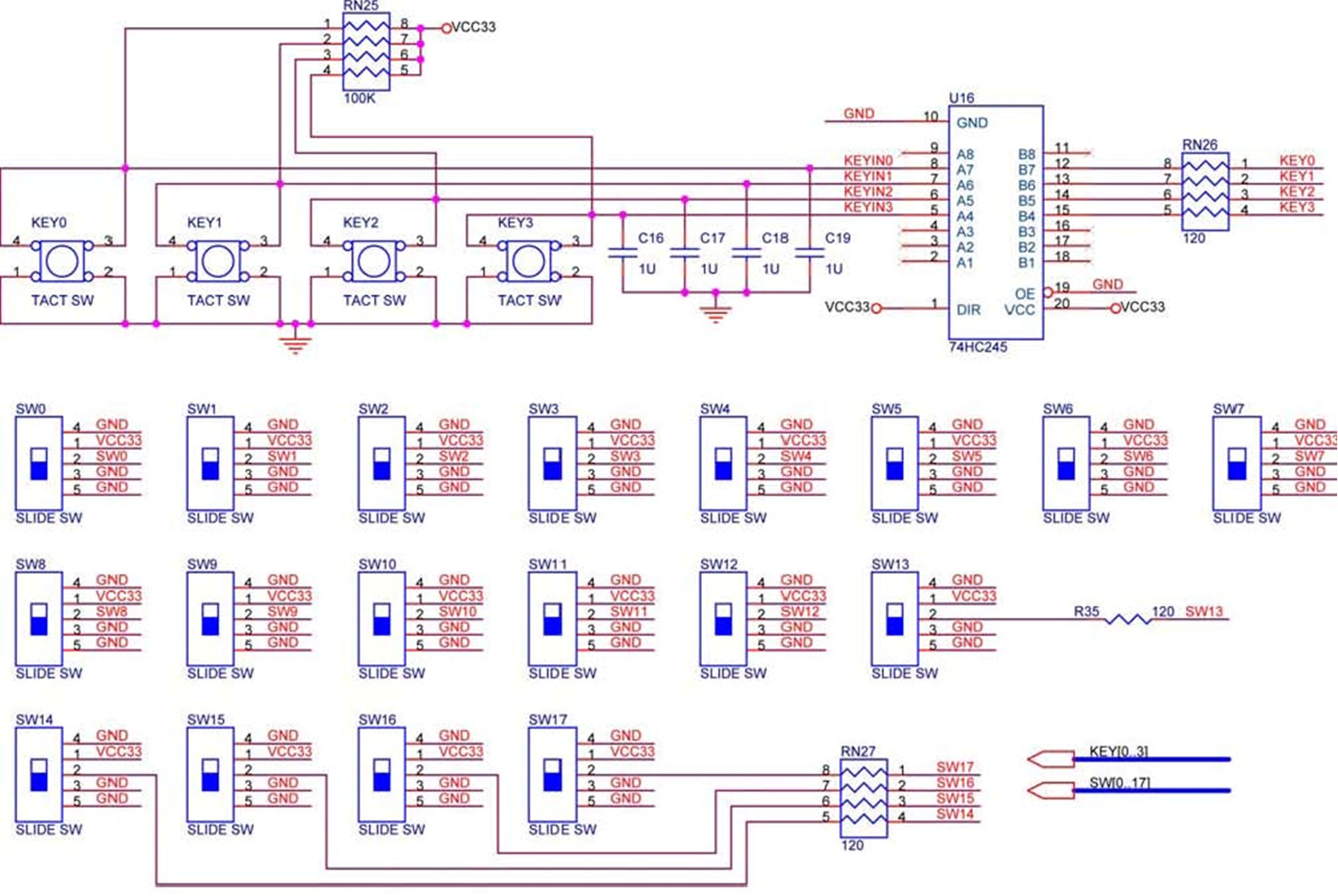
Overall, the DE2 board's design, with its combination of debounced pushbutton switches, toggle switches, and user-controllable LEDs, provides a robust platform for developing and testing digital circuits, making it an invaluable resource for electronics engineers and hobbyists alike. The accompanying schematic diagrams further enhance understanding by visually representing the connections and functionalities of these components.The DE2 board provides four pushbutton switches. Each of these switches is debounced using a Schmitt Trigger circuit, as indicated in Figure 1. The four outputs called KEY0, . , KEY3 of the Schmitt Trigger device are connected directly to the Cyclone II FPGA. Each switch provides a high logic level (3. 3 volts) when it is not pressed, and provides a low logic level (0 volts) when depressed. Since the pushbutton switches are debounced, they are appropriate for use as clock or reset inputs in a circuit. There are also 18 toggle switches (sliders) on the DE2 board. These switches are not debounced, and are intended for use as level-sensitive data inputs to a circuit.
Each switch is connected directly to a pin on the Cyclone II FPGA. When a switch is in the DOWN position (closest to the edge of the board) it provides a low logic level (0 volts) to the FPGA, and when the switch is in the UP position it provides a high logic level (3. 3 volts). There are 27 user-controllable LEDs on the DE2 board. Eighteen red LEDs are situated above the 18 toggle switches, and eight green LEDs are found above the pushbutton switches (the 9th green LED is in the middle of the 7-segment displays).
Each LED is driven directly by a pin on the Cyclone II FPGA; driving its associated pin to a high logic level turns the LED on, and driving the pin low turns it off. A schematic diagram that shows the pushbutton and toggle switches is given in Figure 2. A schematic diagram that shows the LED circuitry appears in Figure 3. 🔗 External reference
Related Circuits
Every dedicated DIY enthusiast creates their own electronic dice using LEDs as indicators. This eliminates the need to physically roll dice; simply pressing a button activates the electronic mechanism. The design incorporates safeguards to prevent manipulation for improved outcomes,...
The integrated circuit input side contains an oscillating circuit, where the oscillation frequency is determined by the external components L1, C1, and the sensor's equivalent capacitance. The equivalent capacitance increases as the sensor is immersed in liquid. The oscillating...
The basic circuit illuminates up to ten LEDs in sequence, following the rhythm of music or speech picked up by a small microphone. The expanded version can drive up to ten strips, formed by up to five LEDs each,...
The 4017 traffic light circuit connects four legs to the green LED and two legs to the amber LED. This configuration raises the question of whether it could function with only one leg per LED. Each output is activated...
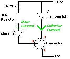
A transistor is an electronic component that allows a small current to control a significantly larger current. This characteristic is valuable in various renewable energy projects and other applications. A basic circuit diagram is provided, featuring a 12V LED...
As a keen cyclist I am always looking for ways to be seen at night. I wanted something that was a novelty and would catch the motorists eye. So looking around at my fellow cyclists rear lights, I came...
Warning: include(partials/cookie-banner.php): Failed to open stream: Permission denied in /var/www/html/nextgr/view-circuit.php on line 713
Warning: include(): Failed opening 'partials/cookie-banner.php' for inclusion (include_path='.:/usr/share/php') in /var/www/html/nextgr/view-circuit.php on line 713