
LIRC receiver
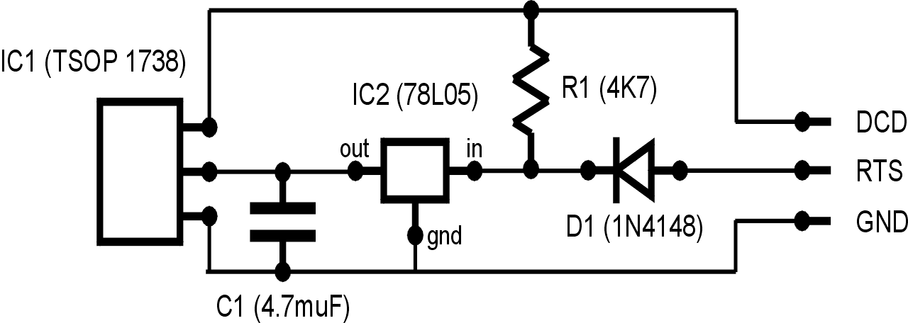
The circuit operates with the RTS (Request to Send) line of the serial port providing the necessary power supply for the voltage regulator. This regulator is crucial for ensuring that the circuit operates at a stable 5 volts, which is essential for the reliable functioning of the connected components. The inclusion of a diode serves a protective function; it prevents any reverse current that could potentially damage the serial port by allowing current to flow in only one direction.
The capacitor plays a vital role in voltage stabilization by filtering any voltage fluctuations that may occur during operation. This ensures that the voltage remains constant, which is particularly important for sensitive electronic components that require a steady power supply. The grounding scheme is also critical; all grounds are connected to the GND line of the serial port, which helps in minimizing noise and ensuring a common reference point for the circuit.
Furthermore, the data output from the IR receiver is interfaced with the DCD (Data Carrier Detect) line of the serial port. This connection allows for the transmission of data signals from the IR receiver to the serial port. The addition of a pull-up resistor from the power line to the DCD line ensures that the line is held high when no data is being transmitted, which helps in maintaining a defined logic level and avoiding floating states that could lead to erratic behavior in the circuit.
Overall, this circuit is designed with simplicity and functionality in mind, effectively utilizing the components to ensure reliable communication and power management within the electronic system.The description of this circuit is rather simple. The RTS line of the serial port gives power to the voltage regulator which fixes it to 5 stable volts. A diode is there to protect the serial port from inverse current. The capacitor helps to keep a stable voltage; all the grounds are bound to the GND line of the serial port.
The data output of the IR receiver is connected to the DCD line of the serial port together with a pull-up resistor coming from the power line. 🔗 External reference
Related Circuits
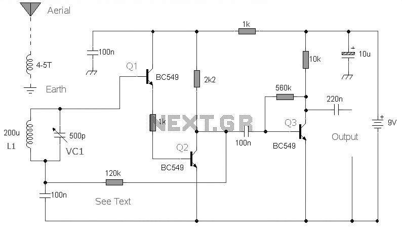
This is the circuit diagram of a mini AM radio receiver. All general-purpose transistors should work in this circuit; BC549 transistors can be used. The circuit utilizes a compact three-transistor regenerative receiver with fixed components. The mini AM radio receiver...
The FM radio receiver with PLL designed by A. Zaharov continues to attract the interest of radio amateurs. According to a publication in the magazine "Radio," one of the primary drawbacks of this type of detector is its low...
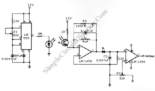
The infrared transmitter and receiver circuit depicted in the schematic diagram can function as a remote control system. The transmitter operates as an oscillator circuit, with the frequency adjustable through the R1 potentiometer (or trimmer pot). This oscillation ensures...
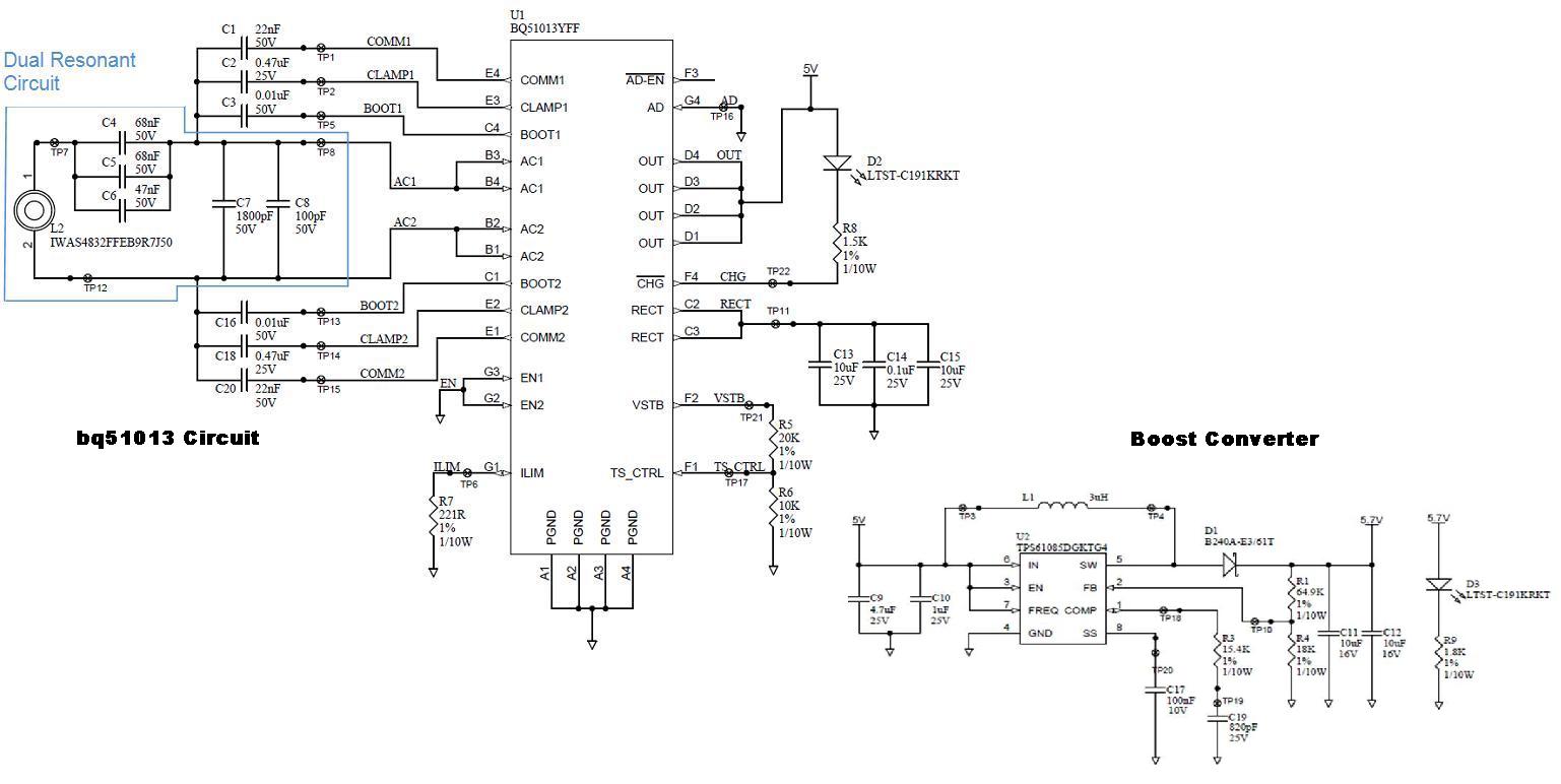
Several boards have been constructed using the bq51013 EVM receiver circuit along with a TPS61085 boost converter circuit, designed in SwitcherPRO Design Software, to elevate the voltage level to 5.7 volts. However, when a load of 580 mA, required...
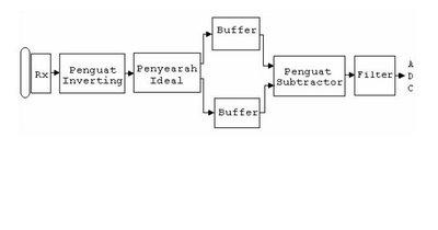
The barrier measurement method for distance is based on assessing the strength of a bound signal. A reflection wave is captured with an acceptor transducer, which emits a sine wave signal. The amplitude of this signal varies with the...
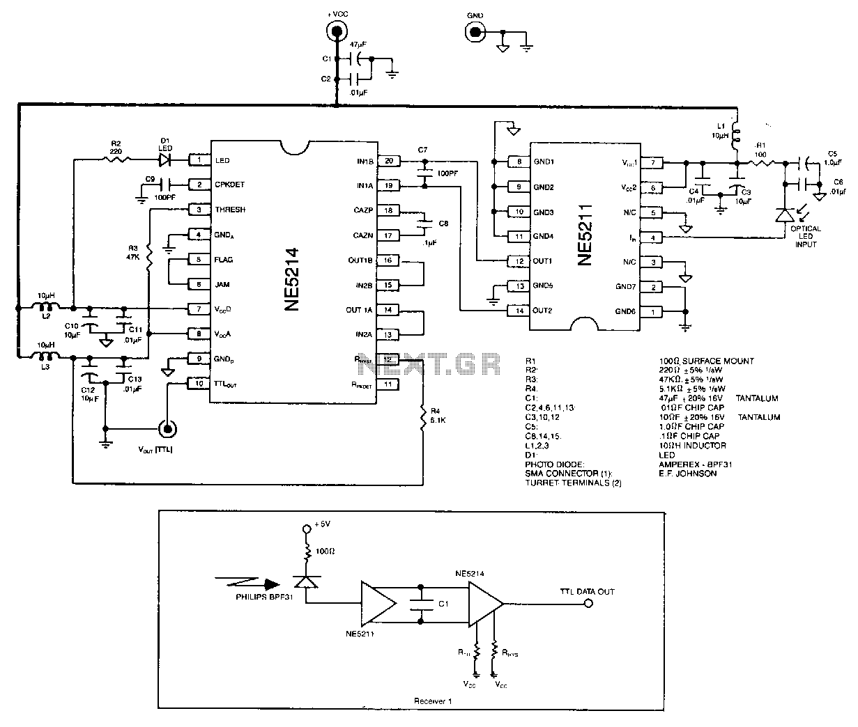
The optical signal is coupled to the pin diode. Current flowing in the diode also flows into the input of the NE5211 preamplifier. The preamplifier is a fixed-gain block that has a 28 kΩ differential transimpedance and performs a...