
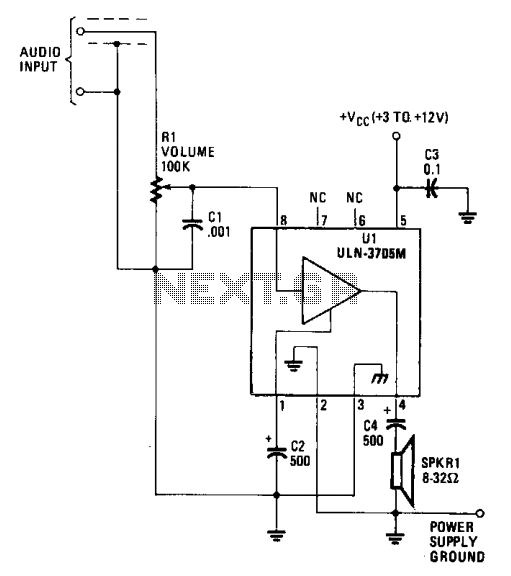
Load Cell Amp
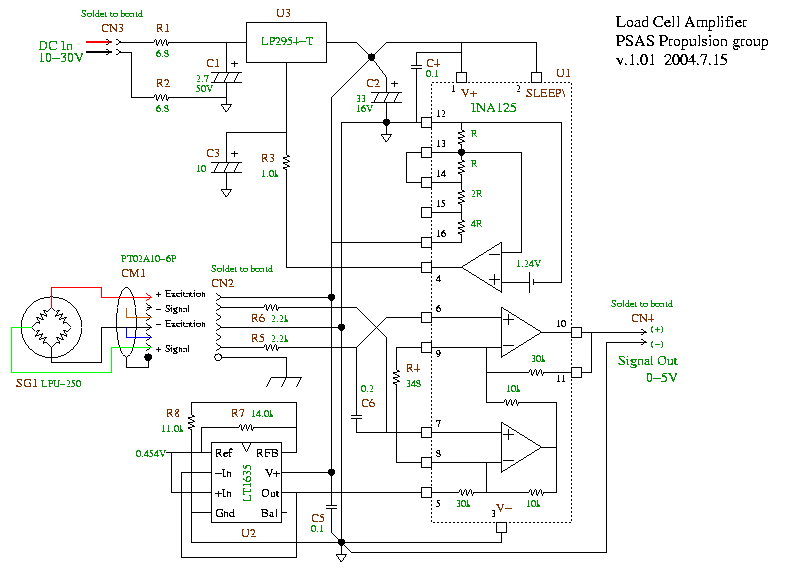
A detailed examination of the circuit reveals a well-structured design aimed at effectively amplifying the low-level output from the strain gauge. The INA125P instrumentation amplifier (U1) is crucial for boosting the signal, ensuring that it reaches the desired voltage range of 0-5V. This is particularly important for interfacing with the PC-based acquisition system, which requires a standard input voltage range for accurate data collection and analysis.
The integrated 1.24V reference within U1 plays a significant role in maintaining the stability of the amplifier's performance. It ensures that the output remains consistent even with fluctuations in the power supply or variations in the load cell's characteristics. The buffer amplifier further enhances the circuit's performance by isolating the load cell from the rest of the circuit, thereby minimizing any unwanted loading effects.
The choice of an 8.75V excitation voltage for the strain gauge is a strategic decision that balances the need for sufficient signal strength with the constraints of operating within a 12VDC power supply. While this lower excitation voltage does introduce some degradation in the signal quality, it is deemed acceptable given the application's requirements. The design effectively utilizes the LT1635 operational amplifier (U2) to create a pseudo-ground reference, which is vital for maintaining signal integrity and preventing clipping, particularly in scenarios where the input signal may be near the ground level due to offset errors.
In summary, the circuit design is robust, employing carefully selected components to ensure reliable operation and accurate signal amplification from the load cell. The availability of schematic diagrams in multiple formats, along with detailed engineering notes, provides essential support for further development and troubleshooting of the system.We have acquired a conventional 250 pound tension / compression load cell (LPU-250) based on a 350 Ohm strain gage bridge. We are in the process of constructing a simple DC-accurate amplifier to convert the low level output of the strain gage to a 0-5V signal suitable for our PC based acquisition system.
Referring to the schematic, the INA125P ins trumentation amplifier (U1) does most of the work. It amplifies the approximately 30mV full scale signal into the required 0-5V range. U1 also includes an accurate 1. 24V reference and buffer amplifier. These are used to drive a low drop out 3-terminal regulator (U3) to produce a stable 8. 75V excitation for the strain gage. 8. 75V was chosen as opposed to the more conventional 10V because we may want to run this amplifier on 12VDC and therefore require the extra headroom. Running the bridge at the lower voltage does degrade the signal somewhat (~14%), but this is regarded as acceptable for this application.
The LT1635 (U2) is an improved LM10 opamp with voltage reference. In this circuit U2 provides a stable pseudo-ground reference level to keep the output signal from clipping against ground even for worst case input offset error. This offset also allows us to read small tension loads if we need to. There are three kinds of file attachments available. The schematic diagrams are provided in source ( xfig ) format and as PDF files as well as in png format above.
The LoadCellAmpNotes. pdf file contains detailed, and mostly accurate engineering notes for almost every component in the amplifier. 🔗 External reference
Related Circuits
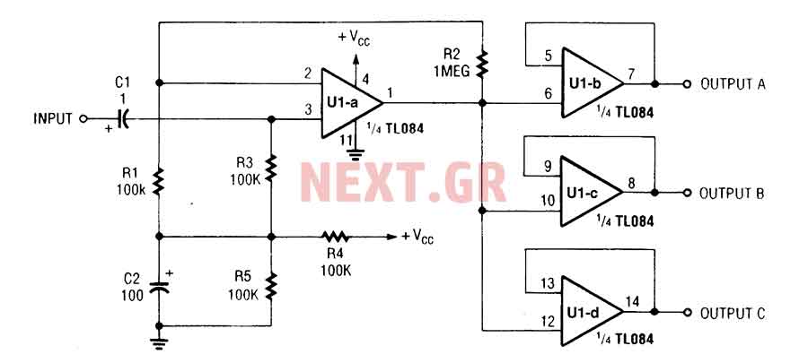
The three-channel amplifier output distribution uses a single TL084. The first step is to capacitive coupling with a 1.0 µF electrolytic capacitor. The entries are railways Vee Y2 or 4.5 V. This allows using a single 9 V power...
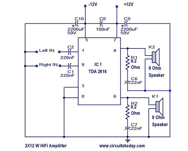
A simple Hi-Fi amplifier circuit diagram with a schematic for creating an audio amplifier design using the TDA 2616 IC. This is a stereo power amplifier suitable for radio, tape, and television applications, delivering 2 x 12 watts, totaling...

The AC negative feedback circuit consists of resistors R and R, as illustrated in Figure 1-30. In this configuration, capacitor C3 can be treated as a short circuit. The actual results are depicted in Figure 1-32. An AC voltage...
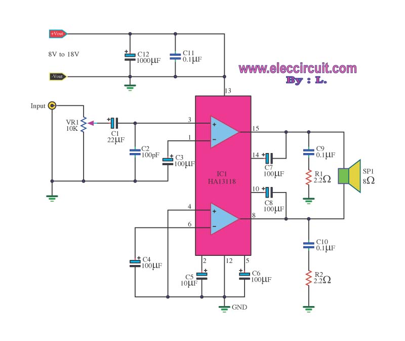
The amplifier circuit utilizes the HA13118 IC, a Hitachi component designed to deliver 18 watts of output power. This integrated circuit operates as a Class AB amplifier. The HA13118 IC is a versatile audio amplifier designed for high-fidelity applications, providing...
The amplifier functions with supply voltages up to 12 volts and can operate at lower voltages as low as 1.8 volts while maintaining acceptable distortion levels, albeit with reduced volume. Its power requirements make it suitable for applications powered...
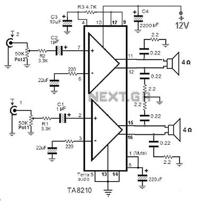
This circuit consists of a 2 x 22 watt BTL amplifier utilizing the IC TA8210AH. It functions not only as an automobile amplifier but is also suitable for low-frequency sound applications, particularly in high-fidelity audio systems, due to its...