
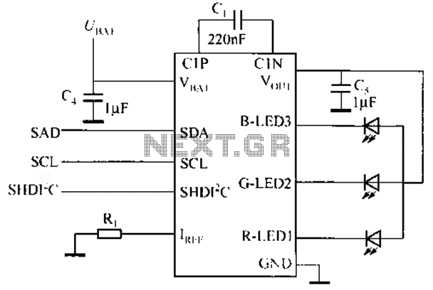
Multi-color LED driver
To achieve additional colors, the appropriate percentage of currents flowing through the two separate channels must be set. This allows for the creation of orange (IR = 21G) and yellow (IG = 2IR) in addition to pure green and red. In this design, the anodes of the dual LED are driven by the outputs of a six-point buffer tri-state technology CMOS. Unlike most integrated circuits in the CMOS 4000 family, the 4503 used here can handle a variety of loads with high currents up to 10 mA. The current flowing to the two diodes is limited by resistors R1 to R6, with specific values that achieve the different colors and varying brightness levels.
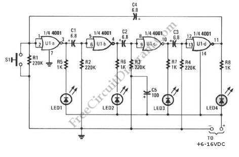
The circuit was originally designed to display three different states, each represented by the presence of a logical '1' in one of the inputs a, b, c. Only one input can be activated at a time, and if none are activated, a NAND gate (IC1c) ensures that the LED produces a fourth color. In the improved version presented here, an additional oscillator (IC1a and IC1b) has been added, generating approximately two pulses per second. These pulses are introduced at the activation input OA (pin 1) of the 4503, resulting in colorful flashes. The oscillator is controlled by logical statements applied to inputs 'd' and 'e'. If both inputs are simultaneously logical '1', then both the oscillator and the buffers of the 4503 remain inoperative. If e = 0 and d = 1, all buffers are driven into a high-resistance state, minimizing current consumption (standby). The power circuit was initially set to 12V, but all components can operate efficiently with any voltage between 5V and 16V.
The circuit schematic features a dual LED configuration that allows the user to explore various color combinations by adjusting the current through each LED diode. The use of a CMOS 4503 buffer facilitates the driving of the LEDs while maintaining low power consumption. The resistors R1 to R6 are crucial for limiting the current to the LEDs, ensuring that they operate within safe parameters while allowing for brightness control.
The oscillator circuit, consisting of two additional CMOS components, introduces a dynamic aspect to the design, enabling the LEDs to flash at a controlled rate. The logical control inputs (a, b, c, d, e) provide flexibility in operation, allowing for different modes of color display based on user interaction. The NAND gate serves as a fallback mechanism, ensuring that the circuit can produce a default color when no other inputs are active.
This design is versatile and can be adapted for various applications, such as decorative lighting, indicators, or educational demonstrations of color mixing and LED operation. The ability to operate across a range of voltages enhances the circuit's usability in different environments, making it suitable for both hobbyist projects and more advanced electronic applications.Have you ever wondered how many different colors can illuminate a LED? One, two or maybe three? Constructing this simple circuit, you will find it much more. The key component in this design is a dual LED. One such accessory includes two inside the 'slices' of different diode LED, that each of them produces a different color (usually green and red). For the drive requires three pins, a common cathode and two separate roots. In this way each of the two integrated diodes can light up as independent of each other. There are only two colors that can produce this dual LED. Setting appropriate percentage of the currents flowing through two separate channels of the POY is, we have other from pure green and red, orange (IR = 21G) and yellow (IG = 2IR). In this design, the anodes of the double LED driven by the outputs a six-point buffer tri-state technology CMOS.
Unlike most integrated family of CMOS 4000, the 4503 used here, can provide a variety of loads on high currents of the order of 1O mA. The stream that goes to the two diodes is limited by the resistors R 1 to A6 whose specific values ??are those that achieve the different colors and changing brightness them.
The circuit was originally designed to display three different situations, each expressed their the presence of logical '1 'in one of the inputs a, b, c. The entries are able to activate only one of each time, and if none of them were excited, a NAND gate (IC1c) made sure that the LED 'to produce fourth color.
In the improved version we present today, the circuit has added another level oscillator (IC 1 a and IC1b), which produces about two pulses per second. The pulses are introduced at the entrance activation OA (pin 1) of 4503, resulting in colorful flashes.
The oscillator is controlled by the of logical statements applied to the inputs 'd' and 'e'. If both are simultaneously logical '1 ', then both the oscillator and the buffers of 4503 remain inoperative. If e = O and d = 1, then all buffers are driven in a state of high resistance and the circuit absorbs the least possible current (standby).
The power circuit was initially set at 12V, but all the components that are able to work equally well with any voltage between 5 and 16 V. 🔗 External reference
Related Circuits
This schematic diagram illustrates a ring-around LED flasher circuit. The circuit operates by turning off two LEDs while activating the other two, continuing this pattern until the timing cycle reverses. The ring-around LED flasher circuit is designed to create a visually...
This project Digital gated Emulator using Microcontroller is used to emulate the basic gates such us NOT, OR, AND. The system has the selector switch by which we can select any gate. The system has two inputs and one...
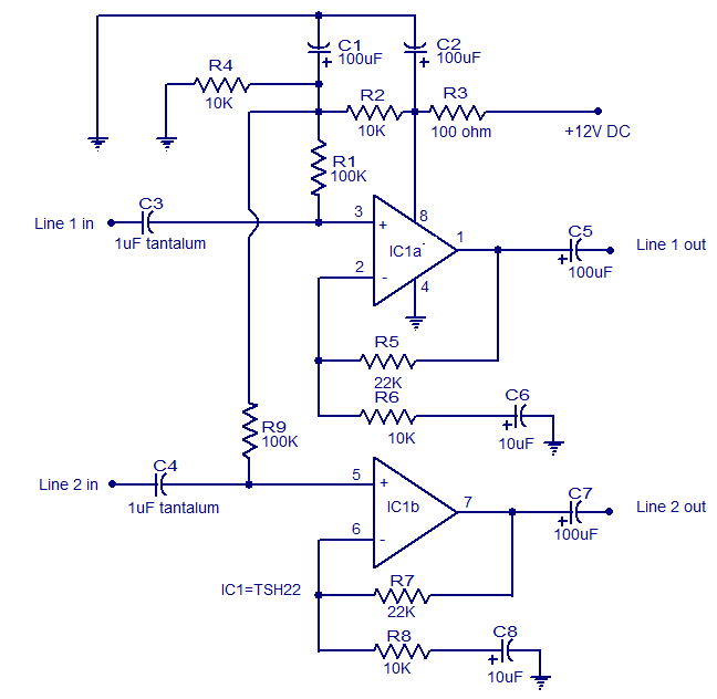
This is the circuit diagram of a two-channel audio line driver utilizing the high-performance dual op-amp IC TSH22 from ST Microelectronics. The IC features a 25 MHz bandwidth, low distortion, and high output current, enabling it to drive medium...
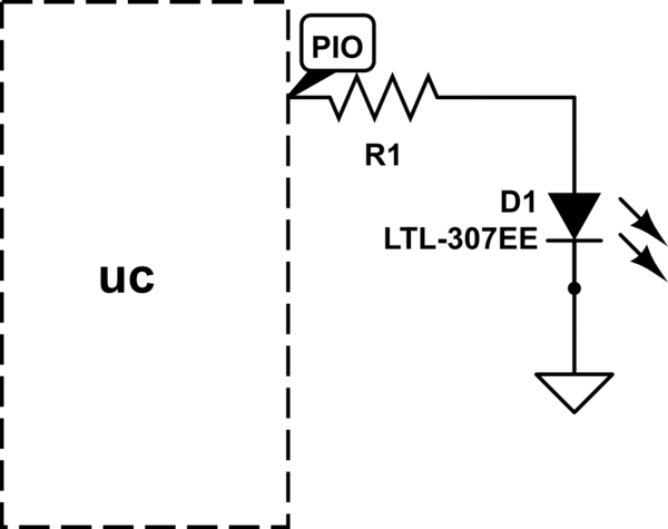
The LED will illuminate when the PIO (Programmable Input/Output) pin goes low, functioning similarly to a ground connection. In this configuration, the current is sourced from the power supply rather than the PIO, as in the first method. It...
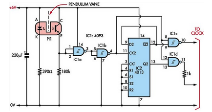
Here is how to build a pendulum-controlled clock that can be made very accurate. Retro? Yes, but it is an interesting project nonetheless. You will need a specific set of components. A pendulum-controlled clock is a mechanical timekeeping device that...
Watching the time on a mobile phone in the dark can cause discomfort due to the strong contrast between bright and dark backlighting. To address this issue, the "ICON" model is utilized, which operates in standby mode with a...