
Old-Time Radio
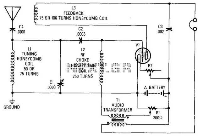
The described circuit represents a simple yet effective early radio receiver design, commonly referred to as a crystal or regenerative receiver. The use of a battery-operated triode, specifically the type 30, is notable for its ability to amplify weak radio signals. This triode operates with a low voltage supply, which is provided by the "A" battery rated at 3 volts.
The rheostat, designated as R2 with a resistance of 100 ohms, serves as a variable resistor in the circuit. It allows for the adjustment of current flow, which is crucial for optimizing the performance of the triode and the overall sensitivity of the receiver. This adjustability facilitates tuning into different frequencies and enhances the clarity of received signals.
Coils in this circuit are constructed using a honeycomb winding technique, which is essential for creating the necessary inductance. The specified diameter of 2 to 3 inches indicates a compact design that is typical for early radio circuits. The honeycomb winding method not only maximizes the efficiency of the coil but also minimizes parasitic capacitance, which can degrade signal quality.
The overall design of this radio receiver circuit emphasizes simplicity, making it accessible for hobbyists and early radio enthusiasts. Its components are readily available, and the circuit can be constructed with basic electronic skills. This circuit exemplifies the ingenuity of early radio technology and its foundational role in the development of modern communication systems. This circuit was used in the early days of radio to receive signals. Almost any battery-operated triode, such as a type 30, can be used. "A" battery is 3 V, R2 is a 100- rheostat. Coils are typically 2" to 3" diameter honeycomb wound. 🔗 External reference
Related Circuits
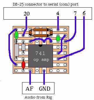
It's a very easy interface to build and requires only a few £/$ worth of components. As you can see by the picture on the right, there's not much to it. To be honest, the picture is misleading. This...
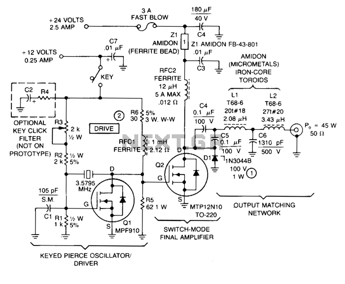
This transmitter comprises a keyed crystal oscillator/driver and a high-efficiency final amplifier, both utilizing a TMOS Power FET as the active component. The total cost of components is under $20, and no specialized construction skills or circuit boards are...

The basic concept involves a transmitter that emits beeps while the user adjusts a directional antenna to determine the maximum signal strength, indicating the direction of the transmitter. The effectiveness of this method is limited due to the antenna's...
Here is the schematic diagram for a very basic crystal radio set without any particular embellishments. This basic old time radio uses no power other than that provided by the transmitting antenna from the radio station. Free power from...
The receiver circuit depicted in the figure requires the insertion of a plug into the radio headphone jack. When the radio receiver detects a signal from the transmitter, an audio signal is output from the jack. This signal is...

This circuit represents a remote control unit that utilizes radio frequency signals to operate various electrical appliances. The remote control unit features four channels, which can be expanded to twelve. This circuit stands out from similar designs due to...
Warning: include(partials/cookie-banner.php): Failed to open stream: Permission denied in /var/www/html/nextgr/view-circuit.php on line 713
Warning: include(): Failed opening 'partials/cookie-banner.php' for inclusion (include_path='.:/usr/share/php') in /var/www/html/nextgr/view-circuit.php on line 713