
Optical toggle switch with 4027
The circuit utilizes the dual flip-flop integrated circuit CD4027, which contains two independent flip-flops that can be configured as either RS, JK, or D types. This versatility allows for various applications, including the generation of clock pulses. In this specific application, the circuit eliminates the need for an external 555 timer by employing one of the flip-flops to generate square wave signals directly.
The configuration involves setting up one flip-flop in a toggle mode, where the output changes state with each clock pulse received. The clock pulses can be generated from the output of the flip-flop itself or from an external source, depending on the desired frequency and stability. The output from this flip-flop serves as a square wave generator, providing a continuous stream of pulses that can be used as a timing signal for other components in a larger system.
The second flip-flop can be utilized for various purposes, such as dividing the frequency of the square wave output or as a data storage element in sequential circuits. The CD4027's ability to operate over a wide voltage range (from 3V to 15V) makes it suitable for various applications in digital logic circuits.
Overall, this configuration simplifies the design by integrating the clock generation within the flip-flop IC, thereby reducing component count and enhancing reliability. The resulting circuit is efficient for applications requiring precise timing and pulse generation without the complexity of additional components like the 555 timer.Using dual flip-flop IC CD4027 employ a 555 based monostable circuit to supply input clock pulses. The circuit described here obviates this requirement. One of the two flip-flops within IC CD4027 itself acts as square wave shaper. 🔗 External reference
Related Circuits
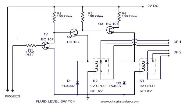
A simple liquid level switch circuit with diagram and schematic. This can also be used as a water level switch, fluid level switch, float level switch, and tank level switch. The liquid level switch circuit is designed to detect the...
This application note describes a digital blood pressure meter concept that utilizes integrated pressure sensor analog signal-conditioning circuitry, microcontroller hardware/software, and a liquid crystal display. The sensing system measures cuff pressure (CP) and extracts pulses for analysis to determine...

The thyristor AC switch circuit is not triggered, due to its simplicity, cost-effectiveness, and non-contact operation, making it widely utilized. The circuit is illustrated in Figure 16-43. It consists of single-phase thyristor switching circuits. Figure 16-43 (a) depicts a...
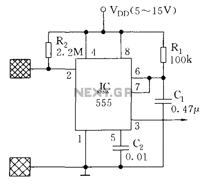
The proximity switch using the 555 timer functions as a monostable trigger circuit. The trigger pin (Pin 2) of the 555 timer is connected through a large resistor (R2) to the positive supply voltage (VDD) and is in a...
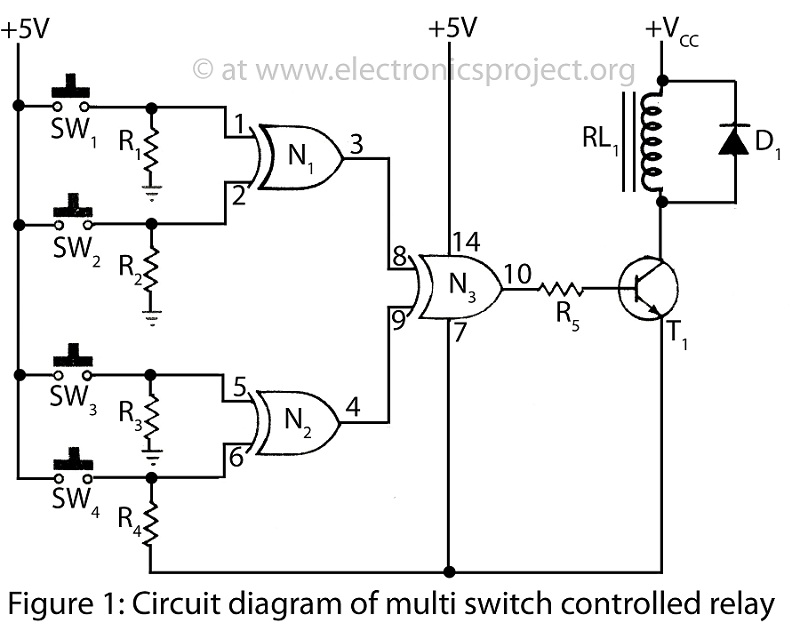
A Multi Switch Controlled Relay circuit is utilized to manage home appliances, featuring a circuit diagram that outlines the application of a multi switch-controlled relay using a single integrated circuit (IC) for various control functions. The Multi Switch Controlled Relay...
This application note describes the creation of a heart rate monitor utilizing an infrared (IR) LED and a phototransistor pair, with the waveform observed at the output of the phototransistor. The purpose of this project is to demonstrate a...