
Overvoltage protection for RS232
Another question is what needs to be protected. The answer is that every communication line wire which is connected between computers must be protected. In the simplest case, there are only transmit data, receive data, and ground lines used. In this case, only protection components are needed: one between transmit data and ground and another between receive data and ground. If more lines are used, then all of them must be protected with a protection component between the signal wire and signal ground. This circuit is based on zener diodes, and the basic idea is quite similar to some commercial circuits also. The zener diode is faster to react to the surges than those VDRs, so they provide better protection. Zener diodes also have lower capacitance than VDRs, so they suit better for high-speed data lines. Unfortunately, the surge capacity of those zener diodes is not very high, so that they can't handle the large spikes by themselves. That's why 10-ohm resistors have been added in series with the data line before the zener diodes. This resistor limits the surge current to a safer value for the zener diode. The resistor must always be between the data line and zener diode, so the circuit must be configured in a way where the computer connects to the connector on the right and the data line to the connector on the left. It is possible to make this circuit "bidirectional" just by adding resistors to the computer side of the zener diodes, but this increases the resistance in the data line. The following circuits are provided here to give an idea of how the overvoltage protection circuits really work and how protection can be easily added to circuits. To make these circuits really effective, careful component selection and good construction are necessary. For best performance, it is recommended to use commercial units from reliable data communication product manufacturers. In bad overvoltage situations, it is recommended to use galvanic isolators in serial port lines or use serial data converters which provide isolation and protection (short haul modems, current loop adapters, etc.).
The RS-232C serial port protection circuit typically consists of several key components arranged to safeguard the communication lines. The circuit should include zener diodes, which act as voltage clamping devices, positioned between the signal lines (transmit and receive) and ground. These zener diodes should be chosen based on their breakdown voltage, ideally rated slightly above the maximum allowable voltage of the RS-232 standard, which is ±25V.
To enhance the protection mechanism, 10-ohm resistors are connected in series with each signal line before the zener diodes. This configuration serves to limit the current flowing through the zener diodes during an overvoltage event, thereby preventing damage to the diodes themselves. The resistors also help to maintain signal integrity by minimizing reflections on high-speed data lines.
For a basic implementation, the circuit can be designed with two zener diodes for each data line, one for positive voltage clamping and another for negative voltage clamping. The anode of the positive zener diode is connected to the ground, while the cathode connects to the data line. Conversely, the negative zener diode's cathode connects to the ground, and its anode connects to the data line. This arrangement ensures that any voltage exceeding the specified limits is shunted to ground, effectively protecting the connected devices.
In scenarios where multiple signal lines are utilized, such as in multi-drop RS-232 networks, each line must be individually protected using the same zener diode and resistor configuration. Additionally, the overall layout of the circuit should be carefully considered to minimize parasitic capacitance and inductance, which could adversely affect high-speed data transmission.
For applications requiring enhanced protection, galvanic isolation can be implemented using opto-isolators or isolation transformers. This approach not only protects against overvoltages but also eliminates ground loop issues and enhances overall system reliability.
In summary, implementing robust overvoltage protection for RS-232C serial ports is essential in environments prone to electrical surges. By utilizing zener diodes, series resistors, and considering additional isolation techniques, the integrity of the communication lines can be maintained, thereby extending the lifespan of the connected equipment.RS-232C serial port lines are quite prone to be damaged by overvoltages. The damaged to computer serial ports have become more and more expensive to replace because of higher intergaration: usually you have to buy new motherboard if one serial port in it gets broken. So it is wise to use some extra protection in situations where overvoltages surges are quite propabe and repairing gets expensive.
For examples of this type of situations are long serial port lines side the building and situation where the computer is connected to ungrounded outlet or the electricity distribution wiring is is not well organized. Protecting RS-232 serial port against overvoltages usually quite easy. The standard says that the signal can be voltage between +25 and -25 volts, so anything outside this range is not allowed. Typical RS-232C receiver chips can handle well voltages up to +/-30V. So an overvoltage protection which cuts out everyhing above 25V and acts fast is the solution. Suitable components for this are varistors (VDR), zener diodes and other fast semiconductor based overvoltage protection devices.
Another question is what needs to be protected. The answer is that every communication line wire which is connected between computers must be protected. In simplest case there are only transmit data, receive data and ground lines used. In this case only protection componets are needed: one between transmit data and ground and another between receive data and ground.
If more lines are used, then all of then must be protected with a protection component between signal wire and signal ground. This another circuit is based on zener diodes and the basic idea is quite similar to some commercial circuits also.
The zener diode is faster to react to the surges than those VDRs so they provide better protection. Zener diodes also have lower capacitance than VDRs, so they suite better for high speed data lines. Unfortuantely the surge capacity of those zener diodes is not very high, so that they can't handle the large spikes by themselves. That's why I have added 10 ohm resistors in series with data line before the zener diodes. This resistor limits the surge current to safer value for zener diode. The resistor must be always be between the data line and zener diode, so you mut plug this circuit in the way where the computer goes to the connector on the right and the data line to the connector on the left.
It is possible to make this circuit "bidirectional" just by adding also resistors to the computer side of the zener diodes, but this increased the resies resitance in the data line. The following circuit are provded here to give your idea how the overvoltage protecton circuits really work and how you can easily add some protection to your circuits.
To make theose circuit really effective need careful component choosing and good construction. For best performace I recommend using commercial units from realiable data communication product manufacturers. In bad overvoltage situations is is recommended to use galvanic isolators in serial port lines or use serial data converters which provide isolation and protection (short haul modems, current loop adapaters etc.).
🔗 External reference
Related Circuits
Another method that helps program development besides a dot LED as the output device is a serial bit. With a serial transmission to a terminal emulator program, developer may then test program running easier than a dot LED. One...
This is a simple RS232 Serial to USB Converter. The RS232 to USB converter is an essential interface device that allows communication between devices with RS232 serial ports and modern computers that utilize USB ports. This converter is particularly useful...
The ADM3251E is a transceiver that features high-speed operation, 2.5 kV full isolation, and a single channel for RS-232/V.28 communication. This device operates from a single 5 V power supply. The ADM3251E transceiver is designed for robust communication in environments...
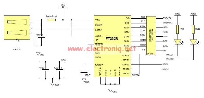
This USB to Serial RS232 adapter is highly beneficial in scenarios where a device with RS232 needs to be connected to a computer lacking an RS232 port but equipped with a USB port. Utilizing the FT232BM chip produced by...
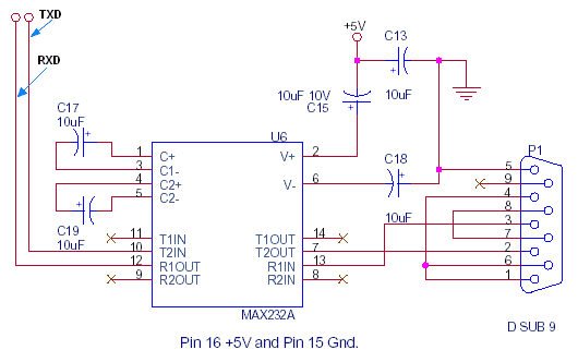
This document outlines the standard configuration for interfacing a microcontroller, such as the 8051, with a PC using RS232 through the MAX232A. The UART or serial port was absent in the 8049 and 8749 microcontrollers, which were predecessors to...
The FM302E-I-type FM transmitter exciter is utilized in Japan's NEC HPB a 1210 motherboard. It features direct carrier frequency modulation, phase-locked frequency stabilization, and frequency synthesis. The preamplifier (BLF-177 FET) is directly driven by an actuator, achieving a maximum...
Warning: include(partials/cookie-banner.php): Failed to open stream: Permission denied in /var/www/html/nextgr/view-circuit.php on line 713
Warning: include(): Failed opening 'partials/cookie-banner.php' for inclusion (include_path='.:/usr/share/php') in /var/www/html/nextgr/view-circuit.php on line 713