
Schematic for the Micro FM transmitter
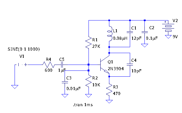
The circuit designed based on Tetsuo Kogawa's documentation utilizes an air variable capacitor (C1) that allows for fine-tuning within the specified range. The choice of 12pF capacitance is a compromise between the maximum capacity of the component and the desired performance characteristics of the circuit. The 9V supply (V2) powers the entire circuit, ensuring that all components operate within their specified voltage ratings.
The modification of the power supply bypass capacitor to 0.1uF enhances filtering capabilities, which can reduce noise and improve stability in the circuit performance. This change is particularly beneficial in audio applications where signal integrity is crucial. The inductor (L1) value of 0.08uH is derived from theoretical calculations for an air-wound solenoid, acknowledging that practical measurements may yield slightly different results due to manufacturing variances and environmental factors.
Replacing the 2SC2001 with a 2n3904 transistor introduces a commonly available and versatile component that is suitable for various applications, including amplification and switching. The transistor's characteristics will influence the overall performance of the circuit, particularly in the modulation stage.
The input signal (V1) simulates a 1000 Hz sine wave, which is a standard frequency for testing audio circuits. This input is critical for assessing the modulation effects on the output signal, which is taken from the emitter of Q1. By monitoring this output, insights can be gained into the circuit's response to varying input conditions.
Future experiments are anticipated to focus on quantifying the deviation in the circuit's performance and exploring methods for control. Additionally, the impact of changing the supply voltage to 6V on biasing and overall circuit behavior will be investigated, which may provide valuable insights for optimizing performance in practical applications. This systematic approach will contribute to a deeper understanding of the circuit dynamics and potential enhancements.Tetsuo Kogawa`s circuit is pretty well documented, but not in conventional schematic form. I decided to enter it into LTSpice to see what it could make of it, and decided to go ahead and put the schematic online here, with perhaps a few comments: I`ve set this up more or less as I built the circuit: in my circuit C1 is a small air variable cap tha t goes up to about 18pF, so I`ve set it to 12pF here. I use a 9V supply, so that`s what I put in for V2. I changed the power supply bypass cap to be 0. 1uF instead of 0. 01uF, since I have a bag of 0. 1uF ones, and it doesn`t seem to affect the circuit. The L1 value of 0. 08uH was determined by plugging numbers into the formula for an air wound solenoid coil: it`s probably only very roughly what the inductance actually is. Instead of the 2SC2001, I went ahead and put in the 2n3904 that I used. V1 is supposed to model the audio input, supplying a 1000 Hz, 1V amplitide sine wave to the modulation input.
The output should be tapped from the emitter of Q1. I`m going to experiment with the circuit a bit more: I`m particularly interested in jigging this up so I can figure out what the deviation is likely to be, and how it can be controlled, and how the biassing might change with a 6V supply. 🔗 External reference
Related Circuits
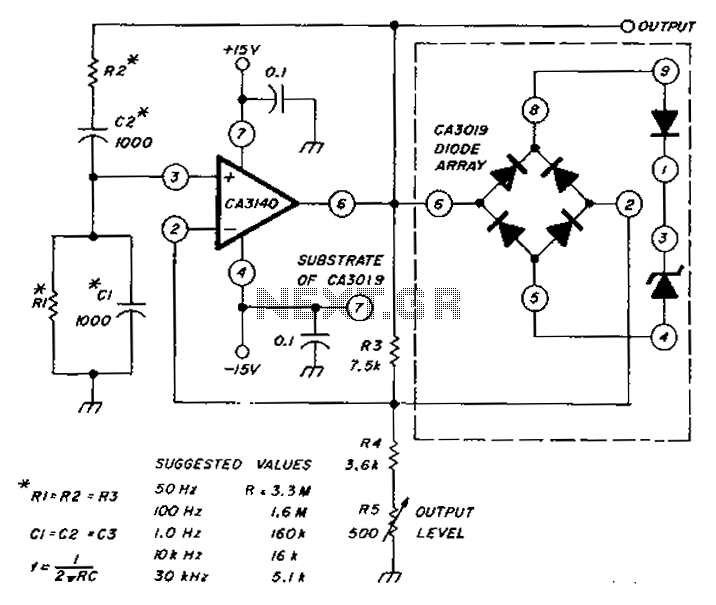
The circuit diagram utilizes a CA3140 operational amplifier and a diode array to generate a low distortion sine wave. A table specifies the values of resistors (R) and capacitors (C), enabling frequency access ranging from 50 Hz to 30...
Using a magnetic compass, ensure that both pickups have a South polarity on the top of each pickup. Verify this by checking for a North polarity on the bottom of the pickups. It is uncommon to find both pickups...
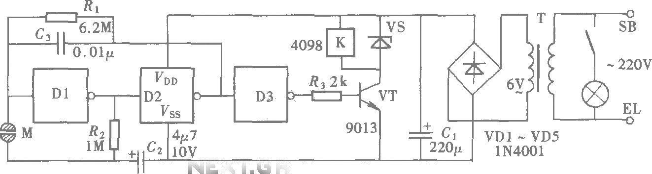
A CMOS gate exhibits high input impedance, which allows it to respond to changes in input levels due to human contact, thereby triggering the toggling of gates. The circuit utilizes this characteristic to create a touch lamp switch. The...
This is a three-stage discrete amplifier with gain control. Alternative transistors such as BC109C, BC548, BC549, and BC549C may be used with minimal impact on performance. The first stage, built around Q1, operates in a common base configuration. While...
These are plans for an EMP generator. It utilizes flash circuits from disposable cameras to power the coil. An instructable will be created soon. The EMP generator design described involves utilizing the high-voltage flash circuits found in disposable cameras. These...
The fundamentals of crystals have not changed since this article appeared in a 1960 edition of Popular Electronics. The methods for growing, cutting, and packaging crystals have evolved significantly. Understanding their operation at the atomic level has also advanced...