
simple automatic street light system
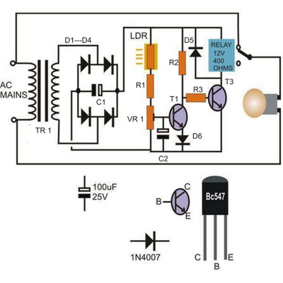
The circuit operates based on the principle of light intensity detection through the voltage comparison between the LDR and the preset resistor. The LDR's resistance varies inversely with the light intensity; as light increases, its resistance decreases, allowing more current to flow through the circuit. The preset resistor serves to adjust the sensitivity of the circuit, enabling it to respond to specific light levels based on the application requirements.
Transistor T1 functions as a key component in determining whether the light level exceeds the preset threshold. When the voltage at the base of T1, influenced by the LDR, surpasses the set threshold defined by the preset resistor, T1 transitions from cutoff to saturation. This transition effectively alters the state of transistor T2, which is configured as an inverter. The output of T2, therefore, directly controls the relay, which in turn controls the power to the connected lamp.
The relay acts as a switch, allowing or interrupting the flow of current to the lamp based on the output state of T2. When T1 is in saturation, T2 is turned off, deactivating the relay and thus the lamp. Conversely, when the light level is low, T1 remains off, allowing T2 to remain on and the relay to activate the lamp. This creates a simple yet effective light-activated switch.
For practical implementation, the entire circuit is compactly designed to fit on a vero board, which simplifies the assembly and reduces the need for complex printed circuit boards. The choice of a sturdy plastic box for housing the circuit ensures durability and protection from environmental factors. Special attention should be given to the placement of the LDR to ensure accurate light sensing, as it must be positioned in an area where it can receive unobstructed light. This design is ideal for applications such as automatic lighting systems, where the lamp should turn on or off based on ambient light conditions.The left hand side transistor T1 is rigged as a voltage comparator using a resistive network. The resistor at the upper arm is the LDR and the lower arm resistor is the preset which is used to set the threshold values or levels. T2 is arranged as an inverter, and inverts the response received from T1. Initially, assuming the light level is less, t he LDR sustains a high resistance level across it, which does not allow enough current to reach the base of the transistor T1. This allows the potential level at the collector to saturate T2 and consequently the relay remains activated in this condition.
When the light level increases and becomes sufficiently large on the LDR, its resistance level falls, this allows more current to pass through it which eventually reaches the base of T1. The transistor T1 conducts, pulling its collector potential to ground. This inhibits the conduction of the transistor T2, switching OFF its collector load relay and the connected lamp.
The whole circuit can be built over a small piece of vero board and the entire assembly along with the power supply may be housed inside a sturdy little plastic box. The LDR must be placed outside the box, meaning its sensing surface should be exposed toward the ambient area from where the light level is required to be sensed.
🔗 External reference
Related Circuits

When the light beam that falls on the CDS photocell is interrupted, the transistor (EN3904) conducts, triggering SCR1 (CI06) and activating the alarm bell. SI resets the SCR. The alarm bell should be a self-interrupting electromechanical type. The lamp...

This simple circuit is designed to detect RF radiation leakage from transmitters, faulty connections, broken cables, or equipment with inadequate RF shielding. It is specifically tailored for the 2-meter amateur radio band (144-146 MHz in Europe). The device features...

This document outlines the construction of a simple joule thief circuit. A joule thief is a versatile device, particularly useful for powering LED lights from low-voltage power supplies. It is capable of extracting energy from nearly depleted batteries, making...
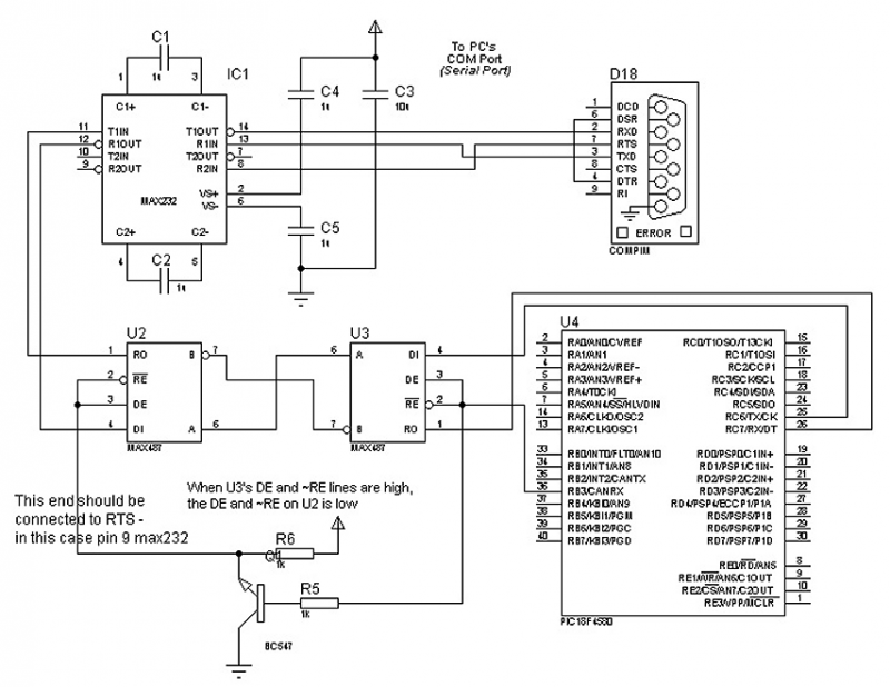
The circuit in Figure 1 is an RS-232/485 converter that uses the transmitted signal itself to control the flow. The circuit uses MAX232 and MAX483 interface circuits, IC1 and IC2 from Maxim Integrated Products to convert between the ICs'...

Assemble the circuit on a perfboard or PCB, excluding the inductor. Attach two long wires in place of the inductor. Use a long rod and position the inductor. The circuit assembly begins with the preparation of a perfboard or printed circuit...
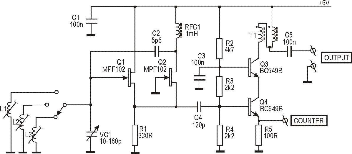
This circuit originated from work on two antenna analyzers, which are detailed elsewhere on this site. Both instruments incorporate an RF signal generator that serves as the signal source for driving the impedance bridge and detectors used to measure...