
SIMPLE HARMONIC DISTORTION ANALYZER
The THD circuit is designed to provide precise measurements of harmonic distortion in audio signals. The operational amplifier TLC272 is selected for its low noise characteristics and high slew rate, making it suitable for audio applications. The twin-T notch filter configuration is effective in attenuating specific frequencies, allowing for the measurement of distortion at the desired frequency range.
The tuning mechanism, utilizing linear-taper slide pots, allows for fine adjustments to both frequency and Q factor, facilitating accurate calibration and measurement. The Q factor, which represents the selectivity of the filter, can be adjusted to suit different testing conditions, providing flexibility in various applications.
For optimal performance, the use of twisted pair wiring minimizes electromagnetic interference, ensuring that the integrity of the input and output signals is maintained. Calibration is critical; thus, the initial setup with a 2000 Hz signal ensures that the circuit is accurately aligned before any measurements are taken.
When in operation, the circuit's ability to detect the lowest output signal during tuning is vital for determining the actual THD. The process of switching between TUNE and TEST modes allows for a straightforward workflow, enabling users to efficiently assess the performance of audio amplifiers or other signal-processing devices.
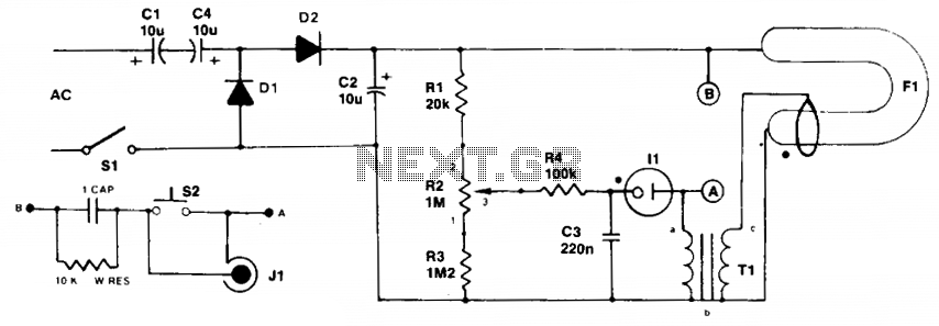
The final calculation of THD percentage is essential for quantifying the distortion present in the signal, providing valuable insights for audio engineers and technicians working to improve sound quality in various electronic devices.This THD circuit is somewhat different from the usual types: it can operate at the standard fre-quency of 1000 Hz, but it also is tunable from 970 Hz to 1030 Hz, and has an adjustable Q factor of 0. 3 to over 50. Op-amp UI, a TLC272 CMOS unit, contains the two voltage-followers required to buffer the input to the bootstrapped twin-T notch filter.
T uning is accomplished by R1, R2, and R3, which are standard linear-taper slide pots "ganged" together by mounting them side-by-side and glu-ing their sliders together. The only other intportant construction hint is to use twisted pair at the cir-cuit`s input and output.
To calibrate the circuit, input a 1000-V RMS signal at 2000 Hz, set 51 to TEST, and adjust R7 for a reading of 0. 99-V RMS on a true-RMS voltmeter at the output. To use the circuit, set 51 to TUNE, input a 1000-Hz sine-wave signal to the amplifier under test, and set the amplifier`s output to the THD adapter and tune R1/R2/R3 for the lowest output signal.
Then, set 51 to TEST and read the RMS voltage. To calculate the percent THD use: 🔗 External reference
Related Circuits
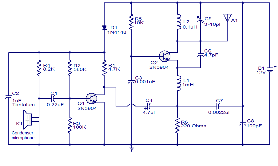
The FM transmitter circuit presented is both stable and simple. With an adaptive antenna, it can achieve a transmission range of approximately 200 meters. This transmitter was developed this year and has yielded positive results. The circuit operates using...

This simple home alarm project can be used with a momentary contact from a motion detector to trigger an alarm similar to a police siren for a duration ranging from a few seconds to 220 seconds. The home alarm project...
Initially, the neon and xenon lamps do not conduct and behave like very high (almost infinite) resistance. Capacitors C1 and C4, in conjunction with diodes D1 and D2, form a voltage doubler circuit, allowing C2 to charge up to...
The basic circuit using the L293 forms an H-Bridge driver, as shown in Figure 1, is designed for controlling inductive loads like DC motors. External diodes are necessary for suppressing back EMF. The MiniBoard utilizes the L293D, which features...
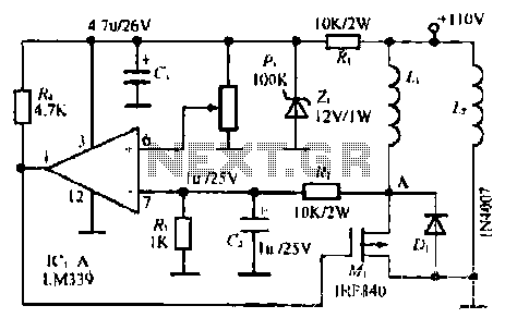
The LM339 comparator IC (Integrated Circuit) is utilized to enhance the functionality of electric circuits. A potentiometer (B) is incorporated to adjust the desired setpoint, while a feedback signal is generated by resistor (R). A significant pressure point is...
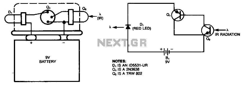
This simple infrared (IR) detector activates a red LED when the transistor Q2 is exposed to invisible IR radiation, commonly found in fiber-optic systems, position sensors, and TV remote-control units. The device can be constructed using a 9V battery...