
Simple Infrared Control Extender
More: The photodiode D4 is connected to the inverting input of a 741 operational amplifier (op-amp) through a resistor (R2) and a capacitor (C1). The BPW41 photodiode, sourced from Vishay/Telefunken, requires reverse biasing to convert light energy into an equivalent voltage; hence, it is also connected to the positive supply rail via resistor R1. The non-inverting input of the op-amp is maintained at half the supply voltage using two equal resistors, R3 and R4. Following the op-amp, a BD240 transistor is utilized as an after-burner, which can supply substantial current pulses to infrared LEDs D2 and D3. It is important to note that the pulsed current through the LD274 infrared emitters should not exceed approximately 100 mA, necessitating the inclusion of a fixed resistor in series with a preset resistor (P1). An additional visible-light LED (D1) is incorporated to flash when an infrared signal is detected from the remote control. Care should be taken when adjusting the setting of P1 to ensure that the current through the infrared emitters does not exceed the minimum required to effectively reach the intended destination of the infrared signal. The currents referenced are peak levels due to the low duty cycle of the infrared pulses; thus, the average current drawn from the battery will be significantly lower. The directivity of the infrared LEDs, and consequently the range of the control extender, can be enhanced by equipping the LEDs with reflective caps.
This circuit effectively extends the range of infrared remote controls by utilizing a photodiode for signal reception and an operational amplifier for signal amplification. The design includes provisions for current limiting and signal indication, ensuring reliable operation while maintaining efficiency. The use of reflective caps on the infrared LEDs can further optimize performance, allowing for greater control distances and improved signal directionality. The careful selection and configuration of components, including resistors and capacitors, contribute to the overall functionality and reliability of the circuit, making it suitable for various consumer electronic applications.Lots of consumer electronic equipment like TV sets, VCRs, CD and DVD players employs infrared remote control. In some cases, it is desirable to extend the range of the available control and this circuit fits the bill, receiving the IR signal from your remote control and re-transmitting it, for example, around a corner into another room.
Photodiode D4 is connected to the inverting input of a 741 opamp through resistor R2 and capacitor C1. Since the BPW41 photodiode (from Vishay/Telefunken) needs to be reverse-biased to turn light energy into a corresponding voltage, it is also connected to the positive supply rail via R1. The non-inverting input of the 741 is held at half the supply voltage by means of equal resistors R3 and R4.
The opamp is followed by a BD240 after-burner transistor capable of supplying quite high current pulses through IR LEDs D2 and D3. However, the pulsed current through the LD274s should not exceed 100 mA or so, hence a fixed resistor is used in series with preset P1.
D1 is an ordinary visible-light LED that flashes when an IR signal is received from the remote. With regard to the setting of P1, do not make the IRED current higher than necessary to reliably reach the final destination of the IR signal. Also, the currents mentioned above are peak levels due to the small duty factor of the IR pulses, the average current drawn from the battery will be much smaller.
The directivity of the IR LEDs and consequently the range of the control extender may be increased by fitting the devices with reflective caps. 🔗 External reference
Related Circuits
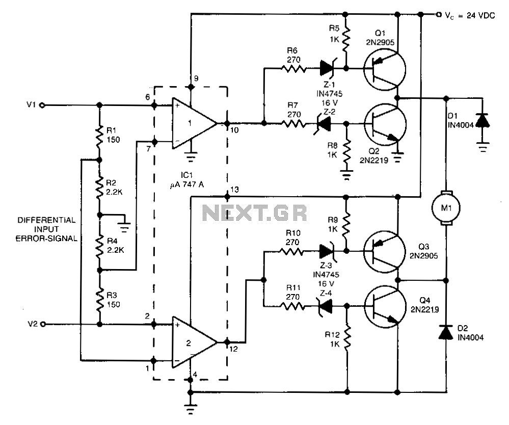
This high-performance switching controller for a low-power DC servo motor utilizes a symmetrical complementary-transistor bridge. The bridge functions as a reversing switch between the motor and a single-ended power supply. Because the transistors operate in a fully on or...
This relatively simple mixer was designed for three dynamic microphones, but can be re-designed for more or less. Level and tone controls are available to tailor the sound to your needs. More: R1-R3 are level controls. R9 and R11...
In this project, we will see how to build a single-channel remote control. It is an easy project to do: by using a pre-assembled radio module, we will get a compact card without sacrificing major performance. The insert function...
This project involves an automatic room light controller with a visitor counter utilizing a microcontroller. It is a dependable circuit designed to manage room lighting while accurately counting the number of individuals present. When a person enters the room,...

The adjustment control for the contrast of an LC-Display is typically a 10-kilohm potentiometer. This functions adequately as long as the power supply voltage remains constant. However, in cases where the power supply is not stable (such as with...

The circuit diagram illustrates a simple stepper motor controller utilizing basic components. The driver circuit employs four SL100 transistors to control the motor windings, along with two NOT gates and one XOR gate to decode the two-bit control logic...