
Simple Phono Preamplifier
The described circuit is a passive high-frequency equalization circuit specifically tailored for moving-magnet cartridges, commonly used in vinyl record playback systems. The circuit is designed to ensure that the audio signal is processed with minimal noise and distortion, while maintaining a faithful reproduction of the RIAA (Recording Industry Association of America) frequency response curve, which is essential for accurate audio playback.
The circuit operates effectively over a frequency range of 1 kHz to 20 kHz, where it performs passive equalization. This is crucial for moving-magnet cartridges, which can exhibit different frequency response characteristics depending on the design and materials used. By employing passive components, the circuit achieves a balance between simplicity and performance, making it an economical choice for audio enthusiasts.
Key components include several resistors (R1 to R8) and capacitors (C1 to C3), which are selected to optimize the circuit's performance. The resistors are rated at 1/4W, ensuring they can handle the power levels typical in audio applications. The values of the resistors are as follows: R1 at 47KΩ, R2 at 100Ω, R3 at 6.8KΩ, R4 at 68KΩ, and both R5 and R6 at 2.7KΩ, with R7 at 2.2KΩ and R8 at 39KΩ. These resistors work together to set the gain and frequency response characteristics of the circuit.
Capacitors C1, C2, and C3, each rated at 100µF and 25V, play a vital role in coupling and decoupling signals, as well as filtering out unwanted noise. The use of electrolytic capacitors is common in audio circuits due to their ability to provide high capacitance in a relatively small package.
The circuit is powered by a dual ±18V supply, which is essential for op-amps used in audio processing. This voltage level enhances headroom, allowing the circuit to handle larger signal amplitudes without distortion. The choice of transistors and their configuration is critical in providing the necessary supply voltage while maintaining low noise levels.
Overall, this circuitry is an effective solution for users looking to enhance the performance of moving-magnet cartridges, ensuring high-quality audio output that meets the demands of modern audio systems.Simple circuitry suitable for moving-magnet cartridges Passive high-frequency equalization. This simple but efficient circuit devised for cheap moving-magnet cartridges, can be used in connection with the audio power amplifiers shown in these webpages, featuring low noise, good RIAA frequency response curve, low distortion and good high frequency transients behavior due to passive equalization in the 1 to 20KHz range. Transistors and associated components provide ±18V supply to the op-amp, improving headroom and maximum output voltage.
R1_________47K 1/4W Resistor R2________100R 1/4W Resistor R3__________6K8 1/4W Resistor R4_________68K 1/4W Resistor R5,R6_______2K7 1/4W Resistor R7__________2K2 1/4W Resistor R8_________39K 1/4W Resistor C1-C3_____100µF 25V Elect 🔗 External reference
Related Circuits
this circuit roughly doubles the voltage of the input, however the current output is low. doubled output is at V source. More: all resistors are 5 or 10 percent tolerance, 1/4-watt all capacitors are 10 percent tolerance. U1 NE555...
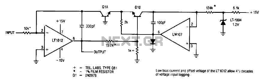
This simple logarithmic amplifier circuit uses the LT1012, which has a low bias current that allows for 4.5 decades of voltage input logging. Additionally, transistors that can be used in this circuit include the 2N2979. The logarithmic amplifier circuit designed...
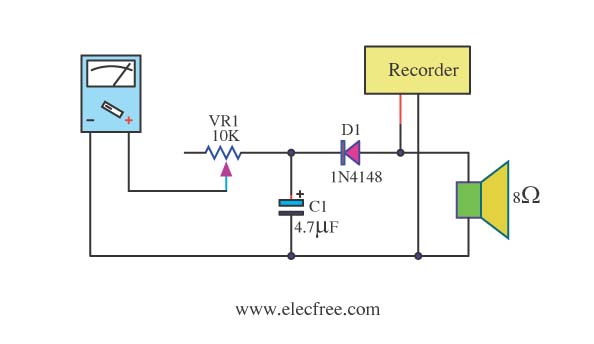
Expensive stereo systems generally feature VU meters that help indicate maximum power levels to prevent overloading. However, typical radio tape players do not include VU meters. A potential solution involves using a multimeter as a replacement. This can be...
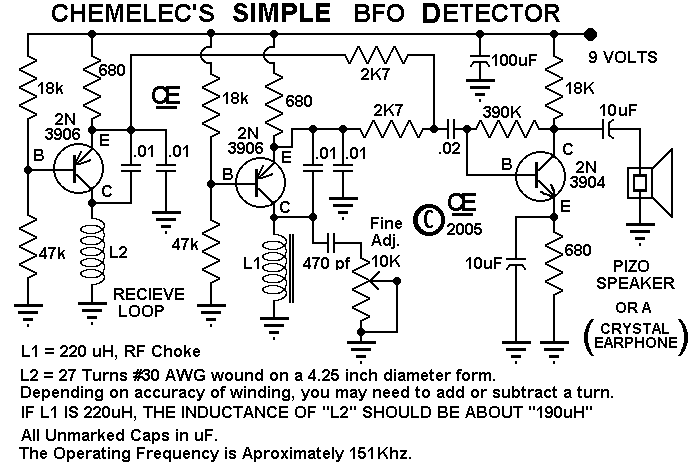
A Very Simple "Beat Frequency Oscillator" type of Metal Detector. These are about the Simplest of all Metal Detector types, But still quite useful for many Detecting applications. And although this one is particularly simple, it works very well. The...
Transistors Q1 and Q2, along with resistors R1 through R7, form the input balancing stage that measures the resistance between points X and Y. This stage operates as a bridge circuit, incorporating resistors R1, R2, R6, R7, and the...
The multimeter should be set to the lowest DC volts range for maximum sensitivity, typically 200mV DC for most meters. The circuit operates effectively at VHF frequencies, approximately 100MHz, yielding satisfactory results. The inductor L1 consists of 7 turns...