
The local oscillator for 10.7 to 2.5MHz conversion
The described oscillator circuit is designed to operate efficiently at high frequencies, utilizing a third overtone crystal to achieve precise oscillation characteristics. The MPSH10 transistor serves as the core amplification component, benefiting from low noise performance due to its emitter configuration. The circuit's architecture emphasizes the importance of maintaining low input and output impedances to optimize the crystal's high Q factor. The LC resonant circuit effectively steps down the output impedance, facilitating better integration with subsequent stages of the system.
The coil design, employing enameled wire and specific dimensions, indicates careful consideration of physical layout and electromagnetic properties, which are critical for maintaining performance at the desired frequency. The use of inductors in series with the emitter resistor and between the emitter and crystal highlights the need for frequency compensation and noise isolation, ensuring that the oscillator remains stable across its operating range.
Feedback mechanisms are incorporated to control oscillations and prevent unwanted high-frequency behaviors, illustrating a sophisticated approach to circuit stability. The ability to lock the oscillator to a frequency standard through diode integration further enhances the usability of this design in precision applications.
In summary, this oscillator circuit exemplifies advanced techniques in RF design, focusing on low noise, stability, and precise frequency control, making it suitable for applications requiring high-performance microwave frequency generation.A 52 MHz third overtone crystal is typically 30 ohms at its series resonance according to manufacturer specifications. The crystals used for the prototypes have nearly ten times lower series resistance but they were very expensive.
An oscillator can be seen as an amplifier which has feedback through a filter. The amplifier of a series resonance os cillator must have both a low input impedance and a low output impedance, preferrably well below the series resonance impedance of the crystal, to preserve the selectivity associated with the high Q of the crystal itself. Since this oscillator is used at a higher frequency the amplitude of the oscillations is controlled by a limiter to make the transistor run in class AB.
This gives a good compromise between the wideband noise floor and the close in phase noise. Class C is good at low frequencies but a bad idea for VHF oscillators, particularly if they are intended to be used to generate microwave frequencies. Class A amplifiers give the best close in performance and should be used for microwave frequency multiplier chains.
The output impedance of the selected MPSH10 transistor is stepped down by a factor of about 20 in a LC resonant circuit. The coil, L14, is 5 turns of 1. 2 mm enameld wire. The coil is wound on a 7 mm rod and mounted self supporting on the PCB with a distance from the copper to the PCB of 3 mm.
The length of the coil is 11 mm. It is essential to feed the amplifier Q5 from a low impedance to make the noise generated in this transistor low. The MPSH10 transistor generates very little noise because of the large current feedback on the emitter.
Except at the frequency of series resonance the impedance seen by the emitter is high and loss-less. The frequency of oscillation is adjusted with a trimmer in series with each crystal and provision is made to add a diode to allow locking the oscillator to a frequency standard. The active MPSH10 transistor is driven into class AB by the power coming through the crystal. The emitter resistor is connected in series with a 10 microhenry inductor to not allow the emitter to see the resistor and the noise from it at large distances from the center frequency.
Adding this inductor makes a clear improvement at a frequency separation of 100kHz. The small inductor between the emitter and the crystal compensates for the tuning capacitor to get the correct frequency of oscillation. It also isolates the emitter from the stray capacitances of the crystal. Some feedback is made from collector to base to prevent UHF oscillations, the collector tuning capacitor is isolated from the collector through a small inductor in parallel with a resistor to allow a collector voltage for this feedback at UHF frequencies.
These pins are intended to be connected directly to the parallel port of the PC for small systems, one separate data pin for each select input with all the other pin`s in parallel. Larger systems need a decoder to convert 6 pin`s to one of 64 pin`s. The frequency control is level controlled and all wires are well decoupled to avoid sending interference into the oscillator.
The user program is responsible for setting the d-type flip-flops right so only one of the 74HC4053 outputs is at minus 5 volts while the other three are at plus 5 volts. At a low frequency like 10. 7 MHz, frequency stability is good without locking the local oscillator to a frequency reference. Figure 3 shows about 80 minutes of typical behaviour with a warmed up unit. The test signal is from two different HP8657A signal generators which were combined in a hybrid and fed into channel 1 of an RX10700 prototype unit which was connected to a RX2500 unit which in turn was connected to a Delta44 board sampling at 24kHz.
The short term frequency stability of the Linrad hardware is comparable to or better than the stability of the HP generators. The short time frequency drift is probably below 0. 02 Hz/min. An earli 🔗 External reference
Related Circuits
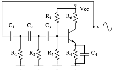
The phase shift oscillator produces a sine wave output in the audio frequency range. Resistive feedback from the collector results in negative feedback due to a 180-degree phase inversion from the base to the collector. The three 60-degree RC...
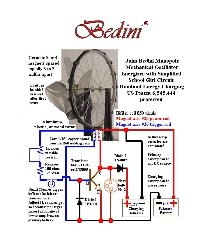
Rick Friedrich, a student of Bedini, demonstrates his setup and results, asserting that by transferring charge from one battery to another using a motor system, this configuration can achieve a net energy gain by harvesting energy from the environment. The...
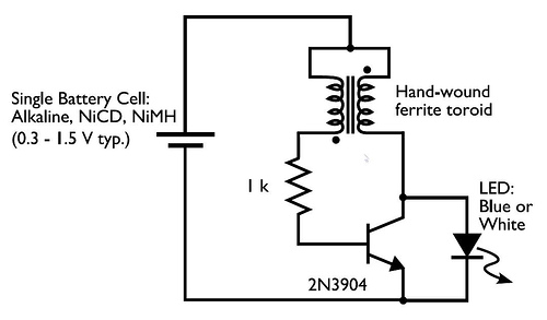
A transformer with two input leads and three output leads was used. An LED was connected to two of the output leads, and when a dead AA battery was connected to the input leads, the LED blinked for a...
This circuit eliminates the traditional tungsten filament lamp amplitude regulator along with its associated time constant and linearity issues. Additionally, it addresses the reliability problems commonly found with lamps. The Wien Bridge oscillator is utilized, leveraging the fact that...
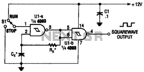
Two gates of the Quad 4093 are utilized to create an oscillator. The resistor (R) can range from approximately 5 kΩ to around 10 kΩ. The capacitor (Cx) can vary from about 10 pF to higher values, with the...
This circuit operates at 36V with a current of 500mA on the front side, while it features a 36V charging capability on the back side. The brightness is comparable to that of a 240V light bulb, considering it is...