
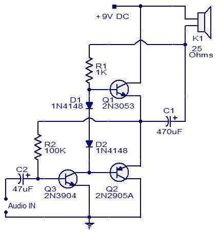
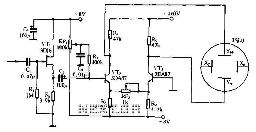
Three transistor audio amplifier
Inquiries have been raised regarding the use of a 16V rated capacitor as a replacement for C1 and C2, which are specified to be rated at 15V. Additionally, questions about connecting a speaker to the input of the circuit to function as a microphone have been posed. There is also a request for advice on the appropriate amplifier capacity for a 400W speaker and whether a capacitor should be installed on the speaker, as well as the desired capacitance value.
For a project involving a combinational circuit of BJTs and FETs, an amplifier circuit with three stages has been proposed, based on the circuit described above. A 10K potentiometer can be utilized for volume control, with the negative terminal of C2 connected to the slider of the potentiometer. One end of the potentiometer should connect to the common (emitter of Q3), and the input should be connected to the common, with the other end of the potentiometer left free.
Minor modifications include changing resistor R1 to 390 Ohms and adjusting the base bias resistance R2 of Q3 from 100K to a 100K preset resistance. A supply voltage of 4.5V (using three AA cells) should be applied without any input signal, and R2 should be adjusted until the emitter voltage of Q1 and Q2 relative to the common negative reaches 2.25V.
The circuit has been tested with various capacitor values, including a 100 pF capacitor between the collector and emitter of Q3, and a 3.3 µF capacitor in place of C2. However, these changes did not yield significant differences in performance. The term "common" is assumed to refer to ground, and it is suggested that the circuit layout is verified for accuracy.
Issues have been reported concerning crackling and static noise when the power is turned on, despite the circuit being wired correctly. It is noted that the amplifier seems to attempt to play audio, but interference is present. The transistors utilized were sourced from a different circuit board, and while they are of the correct type, switching them did not resolve the noise issue. The speaker impedance was adjusted from 8 Ohms to 25 Ohms (three 8 Ohm speakers in parallel), but no improvement was observed.
The amplifier is designed to deliver 100 mW of power, necessitating a drive current of approximately 70 mA with a 25 Ohm load. The output transistors should remain cool during operation. If using speakers with different impedance, it is advisable to incorporate a heat sink or emitter resistance to manage thermal performance.This is the circuit diagram of a simple three transistor audio amplifier that can deliver around 100mW power to a 25 Ohm speaker. The diodes D1 and D2 provides a constant bias voltage for the transistors Q1 and Q2. The transistor Q1 works as a preamplifier. Transistors Q2 and Q3 drives the speaker. The type no of the transistor is not very crucial here. You can use any NPN transistor for Q1, Q3 and any PNP transistor for Q2. Any way the minimum collector current capacity of the transistors must not be less than 100mA. The circuit will work well with an 8 ohm speaker too, but the volume will be a little less. I have two question. (1) can 16v rated capacitor replace the C1, C2. Because you said c1, c2 must be rated 15V. Then, secondly can we connect a speaker to the input of this circuit to make it a microphone I have two question. (1) can 16v rated capacitor replace the C1, C2. Because you said c1, c2 must be rated 15V. Then, secondly can we connect a speaker to the input of this circuit to make it a microphone hi can i ask if how much capacity of an amplifier would i use in a 400W speaker and should i install a capacitor on my speaker how much capacity should i put on the speaker pls i need your advice tnx our assignment is to make a combinational circuit of BJT and FET.
at first we are to submit an amplier circuit with three stages. and we pass the circuit above. Hi RKH you can use a 10K potentiometer for volume control connect C2 negative terminal to slider of the potentiometer. one end of the potentiometer to common (emitter of Q3. now connect the input to common and and other (free) end of the potentiometer. Hi Raj, No major change is required. keep the same circuit assemble and change R1 to 390 ohms and change the Q3 base bias reistance R2 100K to 100k preset resistance.
feed 4. 5 volt (3 X AA cells) supply without any input signal adjust R2 till the Q1 Q2 emitter voltage with respect to common negative reaches 2. 25 volt. now the amp is ready for use. Thanks for replying. The diode polarities are correct. I put a 100PF capacitor between the collector and emitter of Q3, but i didn`t notice a difference. for C2 I was using a 3. 3uF capacitor instead of 4. 7, but I don`t think it makes a difference. and I did hook up a disc capacitor (not quite 470PF) between the base if Q3 and ground. I was guessing that common` meant ground. Correct me if I`m wrong. It still is basically the same as before. Do you have any other ideas as to what I am doing wrong Thank you again for your help. Hi and thanks for posting the circuit here. I am having a bit of trouble with it tho, and I was hoping you might be able to help me. I`m pretty sure I`ve got the circuit wired properly but when I turn the power on I get a lot of crackle and static so that you cant here the song properly.
I can tell that the amp is trying to play the song, but there is so much interference or something that is hindering it. I`m wondering if you know the reason why. I am using transistors that I pulled off a random circuit board, but they are the right type. I`ve switched a couple of the transisors, but I still get the same noise, even tho it does sound a bit different.
I was using an 8 ohm speaker, and I changed that to 25ohm speaker (three 8 ohms wired together) and I didn`t see a difference. From my litle experience with building circuits before, it sounds like I`m missing a connection or two, but I`ve double checked the circuit and I don`t see an error.
Do you have an idea of what I`m doing wrong or how I could fix this. Thanks so much for all your help. Hi Islam the amplifier is designed for 100mw power. that is with 25ohms load it requires a drive current of around 70mA. The out put trasistors will be cool running. If you want to use anyother impedance speaker you have to provide heat sink/emitter resistance to output t 🔗 External reference
Related Circuits
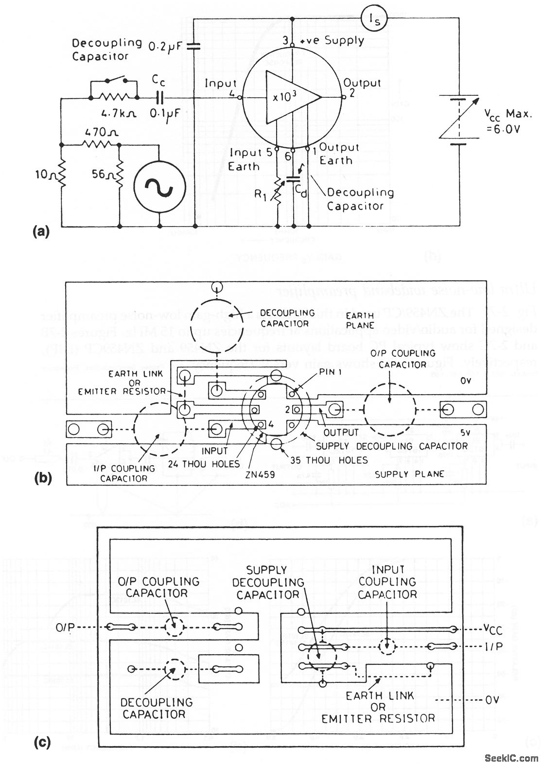
The ZN459/CP utilized in this circuit is a high-gain, low-noise preamplifier intended for audio and video applications at frequencies reaching up to 15 MHz. Figures 2-7B and 2-7C illustrate typical printed circuit board layouts for the ZN459 and ZN459CP...
Many low-power SSB (Single Sideband) transceivers and kits lack effective speech processor circuitry, despite the presence of built-in speech processors in most modern HF (High Frequency) equipment. Low-power SSB transceivers are popular among amateur radio enthusiasts due to their compact...
This amplifier features high fidelity (Hi-Fi), high sensitivity, low power consumption, and low distortion, making it an excellent choice for high fidelity sound systems. The process of creating a printed circuit board (PCB) can be accomplished in a few...
Application of the differential amplifier circuit in a simple small oscilloscope. The differential amplifier circuit is a crucial component in the design of a simple small oscilloscope. This circuit is designed to amplify the difference between two input voltage signals...

A subsonic filter is primarily utilized in low-frequency technology. It is commonly employed to eliminate very low frequencies that can cause distortions in music recording or reproduction. A subsonic filter is an electronic circuit designed to attenuate frequencies below a...
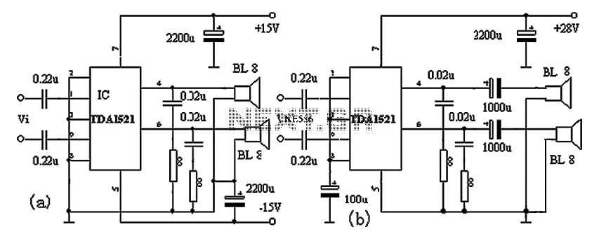
The TDA1521A amplifier circuit is designed for high-fidelity applications with minimal external components. It is suitable for powering Walkman devices or transforming low-powered computer speakers. The TDA1521A comes in a nine-pin single in-line plastic package and offers output power...
Warning: include(partials/cookie-banner.php): Failed to open stream: Permission denied in /var/www/html/nextgr/view-circuit.php on line 713
Warning: include(): Failed opening 'partials/cookie-banner.php' for inclusion (include_path='.:/usr/share/php') in /var/www/html/nextgr/view-circuit.php on line 713