
Tone detector / Sound Activated switch
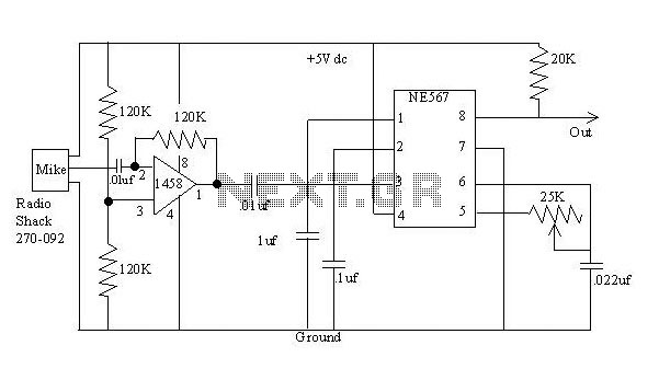
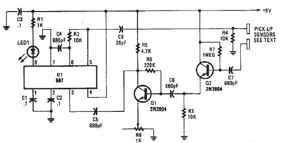
The 567 works by comparing the input signal to an internal oscillator whose frequency is determined by the 25K variable resistor and the 0.022 uf capacitor. These components can be varied as necessary to match the oscillator frequency to the tone generator. A 10 turn pot for the 25K resistor was used, yielding a resistance of about 11K to match the tone generator. The 567 requires a close frequency match to trigger, with the output going low when the frequencies align. Occasional readjustment of the 25K resistor may be necessary for reliable operation, and making this adjustment accessible is advisable in packaged circuits.
The 20K pull-up resistor on the output can be modified or removed to suit processor requirements. The 1uF and 0.1uF capacitors provide filtering and bandwidth adjustment; reference application notes for further adjustments.
Data on the NE567 can be found at http://www-us6.semiconductors.com/pip/ne567d (or if this link becomes obsolete, search for "Phillips Semiconductors").
The 1458 is available at Radio Shack and many other sources.
The circuit described utilizes a standard operational amplifier (op-amp) configuration to amplify an audio signal captured by a microphone. The NE567 tone decoder is employed for frequency detection, enabling the system to respond to specific audio tones.
The op-amp, configured as a non-inverting amplifier, uses the feedback resistor (120K) to determine gain, allowing adjustment of sensitivity to the incoming audio signal. The two 120K resistors connected to the non-inverting input (pin 3) ensure that the output voltage is centered at half the supply voltage, which is crucial for proper amplification without distortion.
The NE567 tone decoder operates by comparing the amplified audio signal against an internally generated frequency, which is adjustable via the 25K variable resistor and the 0.022uF capacitor. This setup allows for fine-tuning to ensure the decoder responds accurately to the desired tone frequency. The close matching of frequencies is critical for the decoder's output to transition low, indicating a successful tone detection.
Capacitors in the circuit, such as the 0.01uF capacitors, serve to block any DC offset from affecting the performance of the amplifier and the tone decoder. Additionally, the 1uF and 0.1uF capacitors provide further filtering, which can be adjusted based on the application requirements.
The output stage includes a 20K pull-up resistor, which can be tailored to the needs of the connected microcontroller or processing unit. This flexibility allows integration with various digital systems, enhancing the adaptability of the circuit design.
In summary, this circuit design effectively amplifies audio signals and detects specific tones, making it suitable for a range of applications, including audio processing and signal detection in embedded systems. Proper component selection and adjustment are essential for optimal performance.The detector (below) is a bit more complex. It amplifies a microphone and sends the resulting signal to an NE567 tone decoder. The amplifier is half of a 1458 opamp. The two 120K resistors attached to pin 3 keep the opamp's average output at about halfway between the 5 vdc source and ground. These resistor values are non-critical, but should be equal. The 120K feedback resistor from pin 1 to 2 establishes the gain of the amplifier and the sensitivity of the detector to a generated tone.
I found that 120K gave me pretty reliable operation at about with the generator about 3 feet from the microphone. You can vary this resistor to make the detector more or less sensitive if you wish. More resistance makes it more sensitive. The two 0.01 uf capacitors are just to eliminate dc voltages. Their values are non-critical. The 567 works by comparing the input signal to an internal oscillator whose frequency is determined by the 25K variable resistor and the 0.022 uf capacitor. You vary these components as necessary to get the oscillator at the same frequency as your tone generator.
I used a 10 turn pot for the 25K which worked fine. The resulting resistance to match my tone generator was about 11K. The 567 requires a pretty close frequency match to trip (the output goes low when the frequencies match). I find that I occasionally have to readjust the 25K resistor to get a reliable trip. You might want to make this adjustment accessible if you package the circuit. The 20K pullup resistor on the output can be changed or deleted to match your processor's requirements.
The 1uf and 0.1uf capacitors provide some filtering and bandwidth adjustment. See the application notes if you want to adjust them. Data on the NE567 can be found at http://www-us6.semiconductors.com/pip/ne567d (or if this link becomes obsolete, search for "Phillips Semiconductors") The 1458 is available at Radio Shack and many other sources.. 🔗 External reference
Related Circuits
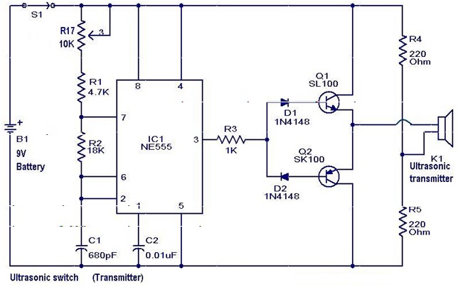
A new type of remote control operates based on ultrasonic sound. The transmitter section of the circuit is constructed around IC1 (NE 555), configured as an astable multivibrator functioning at 40 kHz. The output from IC1 is amplified by...
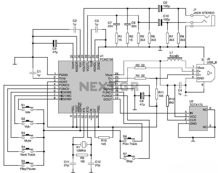
The USB Sound Card circuit is based on the PCM2706, which is designed for USB audio applications. The PCM2706 includes a USB controller module, eliminating the need for additional programming of the integrated circuit (IC). The computer system will...
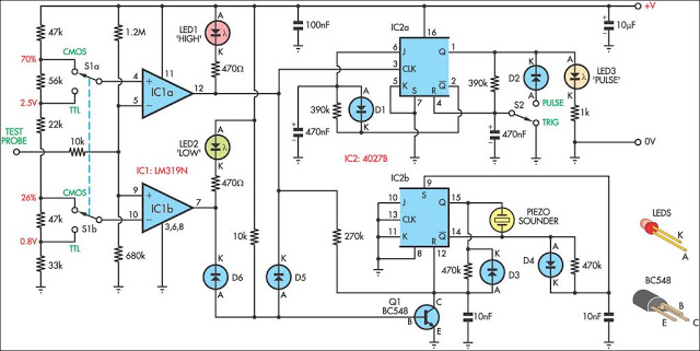
This logic probe can be selected to operate on TTL or CMOS logic levels, depending on switch S1. A string of resistors associated with switch S1 sets the threshold levels for a window comparator comprising IC1a and IC1b. Depending...
A simple proximity detector electronic project can be designed using this schematic circuit. This project utilizes a tone decoder integrated circuit (NE567) that provides a signal with a frequency of approximately 100 kHz. When an object is placed near...
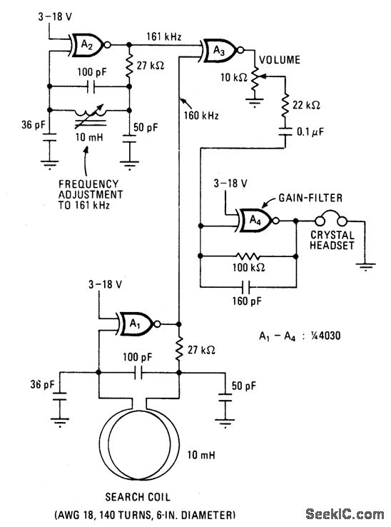
This battery-powered metal detector utilizes four exclusive-OR gates found in the 4030 CMOS integrated circuit. The gates are configured as twin oscillators, with a search coil acting as the inductance element in one of the oscillators. When the coil...
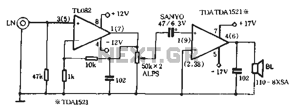
The system includes a CD player, amplifier, speakers, power supply, and headphones. The Mitsumi CD player, designed for the United States, features a 4-speed CD-ROM launched in mainland China in 1997, equipped with an out-of-box key panel for speed...
Warning: include(partials/cookie-banner.php): Failed to open stream: Permission denied in /var/www/html/nextgr/view-circuit.php on line 713
Warning: include(): Failed opening 'partials/cookie-banner.php' for inclusion (include_path='.:/usr/share/php') in /var/www/html/nextgr/view-circuit.php on line 713