
Transistor increases zener rating
In this circuit design, the zener diode serves as a voltage reference and is crucial in maintaining a stable output voltage. When the voltage across the zener exceeds its breakdown voltage, the zener begins to conduct, allowing current to flow through it. However, if the zener diode is of low wattage, it may not be able to handle the required current efficiently, leading to potential failure or inadequate performance.
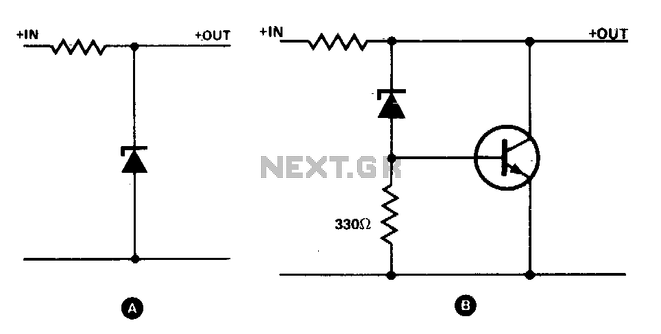
To enhance the current handling capability, a power transistor is integrated into the circuit. The configuration typically involves connecting the zener diode in parallel with the base-emitter junction of the transistor. A resistor, with a value ranging from 330 ohms to 1 kΩ, is connected to the base of the transistor. When the zener conducts, it generates a bias voltage across this resistor. This bias voltage is critical as it turns on the transistor, allowing it to conduct and share the load current.
The output voltage, which is taken from the collector of the transistor, remains at a level that is 0 V greater than the zener voltage. This means that the output voltage is effectively clamped to the zener voltage, ensuring a stable output despite variations in load current. The transistor's ability to handle higher currents allows the circuit to operate efficiently without overloading the zener diode.
This configuration is particularly useful in applications where a stable voltage reference is required, such as in power supplies, voltage regulators, and various analog circuits. The combination of a zener diode and a power transistor provides a robust solution for voltage regulation, ensuring reliable performance under varying load conditions.The simple zener shunt in A may not handle sufficient current if the zener available is of low wattage. A power transistor will do most of the work for the zener as shown in B. Once the zener starts conducting, a bias voltage develops across the resistor (330 O to 1 K), turning on the transistor
The output voltage is 0 V greater than the zener voltage. 🔗 External reference
Related Circuits
Using a single 555 Timer IC and a small transformer to generate a high voltage, this circuit will test zener diodes of voltage ratings up to 50VDC. The 555 timer is used in the astable mode, the output at...

Transistors Q1 and Q2 are configured as a free-running multivibrator. The output at the emitter of Q2 drives the base of the common emitter amplifier Q3, which controls the lamp. This circuit configuration allows for independent variation of flash...
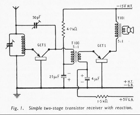
The world's first practical crystal amplifying device was introduced in 1948, marking the beginning of commercially available transistor radios in Britain. At that time, an average radio enthusiast or constructor would have been adjusting to new miniature glass valves,...

None of those devices is very suitable. The drivers aren't specified to operate with 3.3V gate signals, and although the typical graph shows that a... The devices referenced in the original input are not appropriate for the intended application due...
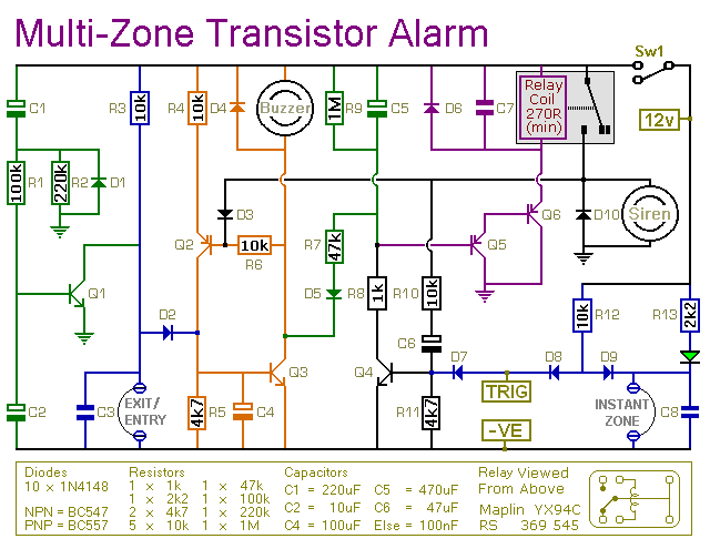
This is a simple transistor-based burglar alarm circuit. Its features include automatic exit and entry delays, along with a timed bell cut-off and reset. It is designed to be used with common types of normally-closed input devices such as...
The driver stage operates similarly to the previously described class A output stage, but it functions at a few milliamps, making efficiency less of a concern. The biasing configuration should be recognizable. Some circuits, including the one mentioned, incorporate...
Warning: include(partials/cookie-banner.php): Failed to open stream: Permission denied in /var/www/html/nextgr/view-circuit.php on line 713
Warning: include(): Failed opening 'partials/cookie-banner.php' for inclusion (include_path='.:/usr/share/php') in /var/www/html/nextgr/view-circuit.php on line 713