
Triple Waveform Generator with 8038
The Tri-Waveform Generator is a versatile electronic circuit designed to produce three types of waveforms: square, triangular, and sine waves. This generator is particularly useful for testing and troubleshooting electronic circuits, providing a reliable source of signals across a frequency range of 20 Hz to 20 kHz.
The frequency of the output waveforms can be finely tuned using a variable resistor labeled R1. By adjusting R1, the user can set the desired frequency within the specified range, allowing for flexibility in testing various circuit responses to different signal frequencies.
Additionally, the duty cycle of the square wave output can be modified using another variable resistor, R4. The duty cycle defines the proportion of time the waveform remains high (active) versus low (inactive) within one complete cycle. This feature is critical for applications where specific timing characteristics are required, such as in pulse-width modulation (PWM) applications.
To ensure the integrity of the sine wave output, which is often used for more sensitive applications, R2 and R3 serve as distortion correction components. These resistors are adjusted while monitoring the sine wave output on an oscilloscope. The oscilloscope allows the user to visualize the waveform and make precise adjustments to R2 and R3, minimizing any harmonic distortion and achieving a clean, accurate sine wave output. This adjustment process is essential for applications that require high fidelity in signal reproduction.
In summary, the Tri-Waveform Generator is an essential tool for electronics testing, providing adjustable frequency, duty cycle control, and distortion correction capabilities to ensure a versatile and reliable signal generation.The Tri-Waveform Generator can be used for a number of different uses. The one that I use it for is a signal generator to test circuits. The frequency range is 20 to 20khz. and can be adjusted by R1. The duty cycle or the time that the waveform is high and the time that the waveform is low can be adjusted by R4. The purpose of R2 and R3 are to clean up any distortion on the sine wave output. To do this you must hook up the sine wave output to and oscilloscope and adjust R2 & R3 to make the sine wave as accurate as possible.
🔗 External reference
Related Circuits
This circuit uses a UM3561 IC to produce four different sound effects. Nothing too complicated here. The IC produces all the sound effects, the output at Pin 3 being amplified by the transistor. A 64 ohm loudspeaker can be...
This circuit generates a stable 1 kHz sine wave using the inverted Wien bridge configuration. The inverted Wien bridge oscillator is a type of electronic oscillator that produces sine waves with high stability and low distortion. It operates on the...
Here is an updated schematic featuring the RF Solutions receiver along with several minor additions. The design includes additional circuitry to manage the signals effectively. The updated schematic incorporates an RF Solutions receiver, which is essential for receiving radio frequency...
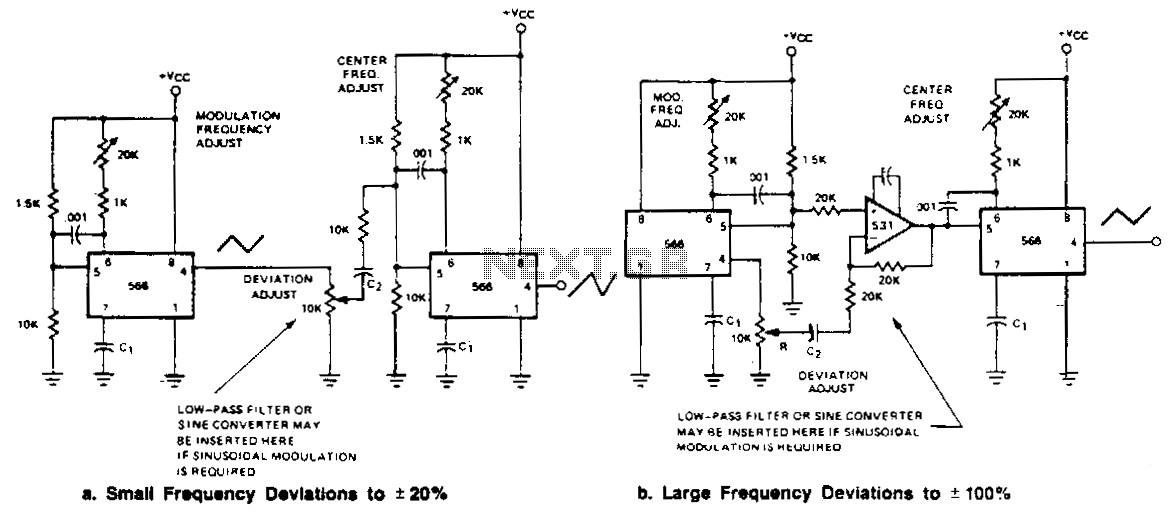
Two FM generators are presented for low frequency applications with a center frequency of less than 0.5 MHz. Each generator utilizes a 566 function generator as a modulation generator and a second 566 as the carrier generator. Capacitor C1...
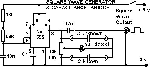
This project integrates multiple features into a compact unit. The core driver is based on an NE555 square wave generator. During development, the idea of building a square wave generator using discrete components was considered, but experiments revealed that...
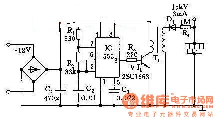
This high voltage generator is capable of producing a stable high voltage exceeding 8kV. The circuit design is straightforward, ensuring stability and reliability. It consists of a step-down rectifier, a voltage regulator circuit, an 18kHz multivibrator-type oscillator, and a...
Warning: include(partials/cookie-banner.php): Failed to open stream: Permission denied in /var/www/html/nextgr/view-circuit.php on line 713
Warning: include(): Failed opening 'partials/cookie-banner.php' for inclusion (include_path='.:/usr/share/php') in /var/www/html/nextgr/view-circuit.php on line 713