
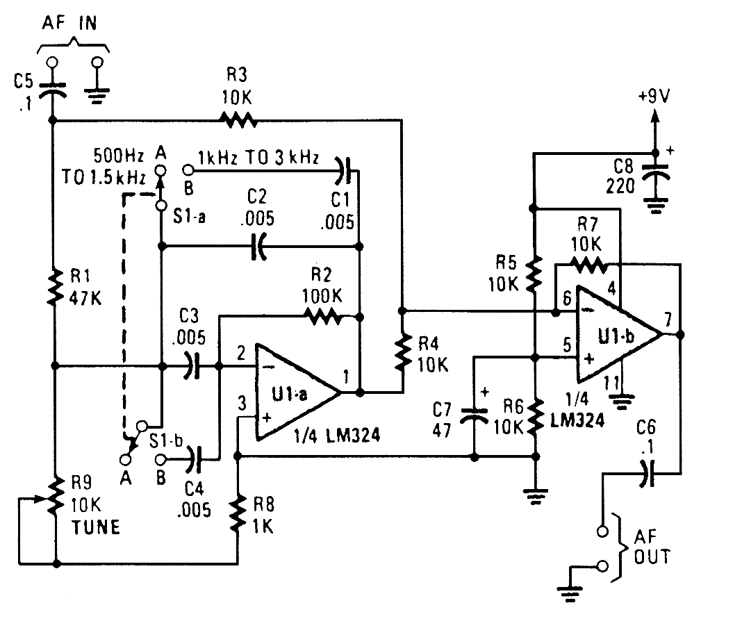
Tunable Bandpass Filter
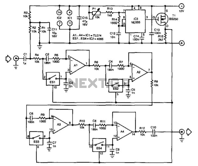
The described circuit is a sophisticated implementation of a tunable bandpass filter utilizing switched capacitor technology to enhance performance and reliability. The 555 timer oscillator serves as the core timing element, generating a precise square wave signal that controls the switching of electronic components. This oscillator's output frequency can be fine-tuned, allowing for versatile application across various audio frequencies.
The electronic switches, identified as ES1 through ES4, play a critical role in modulating resistance within the filter circuit. By effectively acting as variable resistors, these switches enable dynamic adjustment of the filter's characteristics in real time. The design ensures that when a switch is activated, its low resistance allows signal flow, while its high resistance when deactivated prevents signal loss, maintaining the integrity of the filtering process.
The operational amplifier’s configuration is integral to the filter's functionality, allowing it to operate efficiently with a single supply voltage. The use of capacitor C1 stabilizes the input signal, ensuring that the op-amp maintains a balanced output. Capacitor C10 further refines the output by blocking any DC offset, ensuring that only the desired AC signal is present at the output.
The fourth-order filter design is particularly advantageous for audio applications, providing a significant gain while maintaining a manageable current draw of 15 mA. This low power consumption makes it suitable for battery-operated devices. The bandwidth of the filter, adjustable via the oscillator frequency, allows it to be tailored for specific audio applications, ensuring optimal performance in various scenarios. Overall, the described circuit exemplifies a practical solution for achieving high-fidelity audio filtering with tunable characteristics. One of the difficulties in the design of higher-order tunable bandpass filters is achieving correct tracking of the variable resistors in the RC networks. The use of switched capacitor networks can obviate that difficulty, as is shown in this filter. The filter can be divided roughly into two stages: an oscillator that controls the electronic switches arid the four phase-shift networks that provide the filtering proper. The oscillator, based on a 555, generates a pulsating signal whose frequency is adjustable over a wide range: the duty factor varies from 1:10 to 100:1.
Electronic switches ESI through ES4 form the variable resistors whose value is dependent on the frequency of the digital signal. The operation of these switches is fairly simple. When they are closed, their resistance is about 60 ; when they are open, it is virtually infinitely high.
a switch is closed for, say, 25% of the time, its average resistance is therefore 240 . "Varying the open:closed ratio of each switch varies the equivalent average resistance. The switching rate of the switches must be much greater than the highest audio frequency to prevent audible interference between the audio and the clock signals. The input signal causes a given direct voltage across CI, so the op amp can be operated in a quasisym-metric manner, in spite of the single supply voltage.
The direct voltage is removed from the output signal by capacitor C10. The fourth-order filter in the diagram can be used over the entire audio range and it has an amplification of about 40, although this depends to some extent on the clock frequency. The bandwidth depends mainly on the set frequency. The circuit draws a current of not more than 15 mA. 🔗 External reference
Related Circuits
A 12dB/oct Butterworth filter circuit is designed to achieve a flat frequency response. The optimal value for the circuit's Q factor is 0.707, which ensures a flat characteristic. The feedback capacitance must be selected to maintain high capacity and...
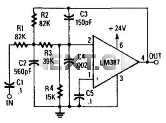
Designed to produce a 12-dB/octave roll-off above the 10-kHz cutoff frequency, this low-pass active filter will help reduce needle scratch on records. It utilizes an LM387 low-noise amplifier integrated circuit (IC). The low-pass active filter described is engineered to attenuate...
In applications where the rejected signal may slightly deviate from the null point in a notch network, it is beneficial to decrease the Q factor of the network. This adjustment ensures consistent rejection across a broader range of input...
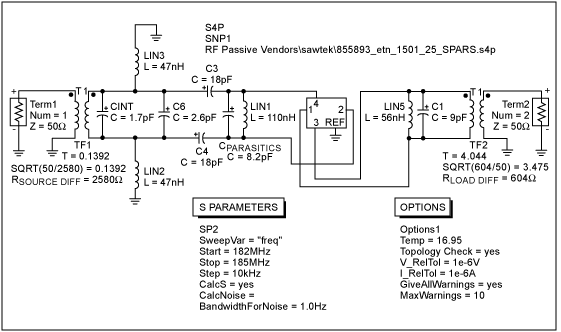
A 183.6 MHz SAW filter is utilized in a CDMA application. The S-parameter of the SAW filter is employed to simulate the interaction with the mixer. An example is provided using the SAWTEK 855893 SAW filter. This application note...
A typical two high-pass filter circuit. A high-pass filter (HPF) is an electronic circuit that allows signals with a frequency higher than a certain cutoff frequency to pass through while attenuating signals with frequencies lower than the cutoff frequency. A...
The notch filter can be integrated into nearly any receiver to attenuate a specific frequency by more than 30 dB. This filter is particularly useful for diminishing heterodynes and whistles. A notch filter, also known as a band-stop or band-reject...
Warning: include(partials/cookie-banner.php): Failed to open stream: Permission denied in /var/www/html/nextgr/view-circuit.php on line 713
Warning: include(): Failed opening 'partials/cookie-banner.php' for inclusion (include_path='.:/usr/share/php') in /var/www/html/nextgr/view-circuit.php on line 713