
Two-speed motor stator winding - connection
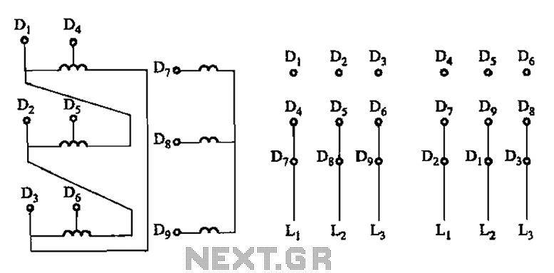
The schematic representation of the two-speed motor's stator winding connection is critical for understanding its operational characteristics. In this configuration, the stator winding is designed to provide two distinct speed settings by utilizing different coil connections. The lead wires from the stator winding are connected to two separate sets of coils, allowing for the selection of either a high-speed or low-speed operation based on the connection configuration.
The two-speed motor typically features a dual winding setup within its stator. Each winding is designed to operate at different voltage levels or impedance values, thereby influencing the motor's speed. The wiring configuration may include a series or parallel connection of the coils, which can be switched using a contactor or a manual switch. This flexibility allows the motor to adapt to various load conditions and performance requirements.
In practice, when the motor is wired for high-speed operation, the coils are connected in such a way that they produce maximum torque and speed. Conversely, when configured for low-speed operation, the connection alters the magnetic field interaction within the motor, resulting in reduced speed and torque output. Proper attention to the connections and the corresponding control mechanisms is essential to ensure reliable operation and to prevent damage to the motor from incorrect wiring.
The schematic should also include details such as the gauge of wire used for the connections, the type of connectors or terminals involved, and any protective devices such as fuses or circuit breakers that may be necessary to safeguard the motor and its associated circuitry. Proper labeling of each wire and connection point in the schematic will aid in troubleshooting and maintenance, ensuring that the motor can be efficiently serviced over its operational lifespan. As shown in Figure 3-109/connection of two-speed motor stator winding lead wire connected coils,
Related Circuits
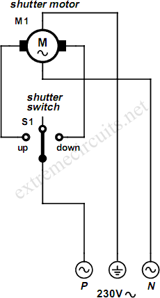
An electrically operated rolling shutter typically features a standard control panel equipped with a three-position switch that allows for up, down, and stop functions. The electrically operated rolling shutter system is designed to provide convenient control over the opening...

This is a simple hobby circuit for a remote-controlled toy car. The primary component utilized is the IR sensor circuit, which includes a TSOP IR receiver. This receiver allows the user to start and stop the DC motor of...
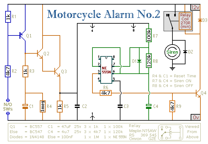
This circuit provides an intermittent siren output with an automatic reset function. It can be manually activated using a key switch or a concealed switch, and it can also be configured to engage automatically when the ignition is turned...
The circuit is based on the SN74LS194 Bidirectional Universal Shift Register and is designed to drive unipolar stepper motors, providing basic control functions such as forward, reverse, stop, and speed adjustment. Direction control is selected by an ON-OFF-ON type...
This is a Class D audio amplifier circuit that is used to control PWM motor speed. This circuit has two advantages for battery-powered portable devices. First, The Class D audio amplifier circuit is designed to efficiently manage the speed...
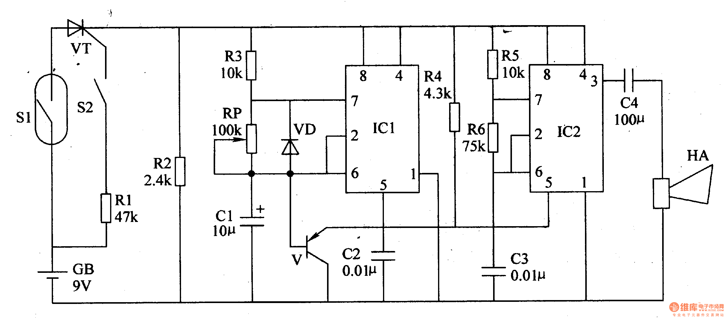
This article introduces a motorcycle anti-theft alarm that utilizes the 555 timer integrated circuit. The alarm is activated when a thief attempts to move the motorcycle vertically. The circuit consists of a trigger circuit and an alarm circuit, as...