
up down fading led
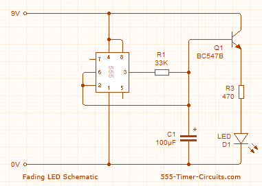
The described circuit utilizes a 555 timer IC configured in an astable mode to generate a PWM (Pulse Width Modulation) signal, which controls the brightness of the LED by varying the duty cycle. The charging and discharging of the 100µF capacitor determine the timing intervals, which in turn affect the fade rate of the LED.
In the circuit, the 555 timer's output pin is connected to the base of a bipolar junction transistor (BJT), which acts as a switch. When the output from the 555 timer goes high, it allows current to flow from the collector to the emitter of the transistor, which is connected in series with the LED. The transistor's gain (beta) allows it to amplify the small base current into a much larger collector current, effectively enabling the LED to receive a higher current than what is supplied from the 555 timer directly.
To achieve the fading effect, the capacitor charges through a resistor connected to the supply voltage (9V). As the capacitor charges, the voltage across it increases until it reaches the threshold set by the 555 timer (2/3 of Vcc). At this point, the output state of the timer changes, causing the capacitor to discharge and the LED to dim. The cycle then repeats, creating a smooth fading effect as the LED transitions from fully off to fully on.
The resistor value of 470Ω is crucial as it limits the current flowing through the LED, ensuring it operates within safe limits while still providing sufficient brightness. The combination of the timing components (resistors and capacitors) connected to the 555 timer determines the fade duration and frequency. Adjusting these components allows for customization of the LED fading effect to suit specific applications or aesthetic preferences.
In summary, this circuit effectively demonstrates the principles of current amplification using a transistor, the timing capabilities of a 555 timer, and the characteristics of capacitive charging and discharging, all working together to create a visually appealing LED fade on and off effect.These two circuits make a LED fade on and off. The first circuit charges a 100u and the transistor amplifies the current entering the 100u and delivers 100 times this value to the LED via the collector-emitter pins. The circuit needs 9v for operation since pin 2 of the 555 detects 2/3 Vcc before changing the state of the output so we only have a maximum of 5.
5v via a 470R resistor to illuminate the LED. 🔗 External reference
Related Circuits
These circuits provide a means of altering the YELLOW output of RED / GREEN type two colour light emitting diodes. These circuits use the LM555 timer chip. The circuit described utilizes the LM555 timer integrated circuit (IC) to modulate the...
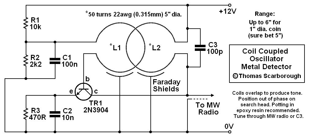
A coil-coupled operation metal detector constructed from commonly available components, utilizing a standard medium receiver as the detection unit. The coil-coupled operation metal detector functions by employing a transmitter coil and a receiver coil that are magnetically coupled. The transmitter...
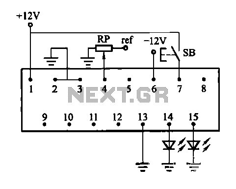
The constant current function module is disabled at the port junction, which has 13 terminals. When the module is turned OFF, the constant current ban port also becomes inactive. The constant current function is lost when the module is...
The Car LED Light Sequencer utilizes a standard 74C164 8-bit shift register as its main component. The 74C164, also referred to as an 8-Bit Parallel-Out Serial Shift Register, is a monolithic complementary MOS (CMOS) integrated circuit. This 8-bit shift...
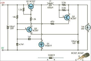
This circuit is designed to drive 1W LEDs that are commonly available. It addresses their non-linear voltage-to-current relationship and variations in forward voltage. The circuit utilizes a constant current driver configuration to ensure that the LEDs operate efficiently while maintaining...
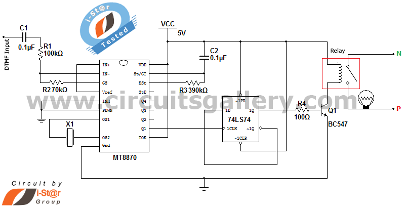
It is possible to control home and office electrical appliances using a mobile phone. This document presents a simple home automation electronic mini project circuit diagram designed for engineering students, allowing the control of electrical appliances without the use...
Warning: include(partials/cookie-banner.php): Failed to open stream: Permission denied in /var/www/html/nextgr/view-circuit.php on line 713
Warning: include(): Failed opening 'partials/cookie-banner.php' for inclusion (include_path='.:/usr/share/php') in /var/www/html/nextgr/view-circuit.php on line 713