
VHF/UHF Wideband Portable Dipole
The described portable dipole antenna is designed for use with VHF and UHF bands, making it suitable for various applications, including amateur radio operations with devices such as the FT-817 transceiver. The antenna's construction utilizes two telescopic antennas, which can be extended to 80 cm for optimal performance and retracted to a compact 14 cm for easy transportation. This design allows for versatility in both horizontal and vertical polarization, enhancing its usability in different environments.
The dipole antenna's core principle relies on its length, which should ideally be a half-wavelength for the desired frequency bands. The use of chrome-plated telescopic antennas aids in reducing weight while maintaining structural integrity, which is essential for portable applications. The choice of materials, including the silver-plated stereo mini switch, is significant as it minimizes signal loss and ensures reliable operation.
The robust PVC enclosure, measuring 75x50x22 mm with a thickness of 1.5 mm, serves to protect the internal components from environmental factors during outdoor use. This enclosure can house the connection points and the switch, allowing for easy toggling between horizontal and vertical polarization without the need for external tools or adjustments.
For assembly, the two telescopic antennas are connected to the PVC box, where the switch facilitates the selection of the desired polarization. The design should ensure that the connections are secure and that the antenna can be easily deployed and retracted as needed. Additionally, the overall design aims to achieve a gain of approximately 3 dB over quarter-wave antennas, providing enhanced performance in signal reception and transmission.
This portable dipole antenna is a practical solution for enthusiasts seeking a reliable and effective antenna for use in various outdoor settings.I wanted a robust, portable, compact antenna usable for horizontal and vertical polarisation to take along with my FT-817 when I go on vacation, camping etc. I also wanted the dipole to cover the VHF and UHF bands and if possible with some gain! As everybody knows a dipole has about 3dB gain over a quartre wave antenna, is why my preference went to a simple dipole.
To make it portable I used two identical telescopic antennas of 80 cm slid out and only 14 cm when pushed in. What you need to make this handy portable wide band dipole is: * Two chrome-plated telescopic antenna`s (14cm/80cm) * A robust PVC box of 75x50x22 mm and 1,5mm thick * a silver plated stereo mini switch 🔗 External reference
Related Circuits
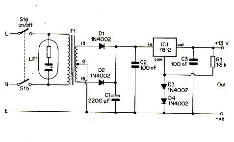
A 12V portable and mobile power supply circuit design that can be constructed at a low cost and requires minimal circuitry. This circuit provides an output current of 1 amp, which is well stabilized and smoothed. The 12V portable power...
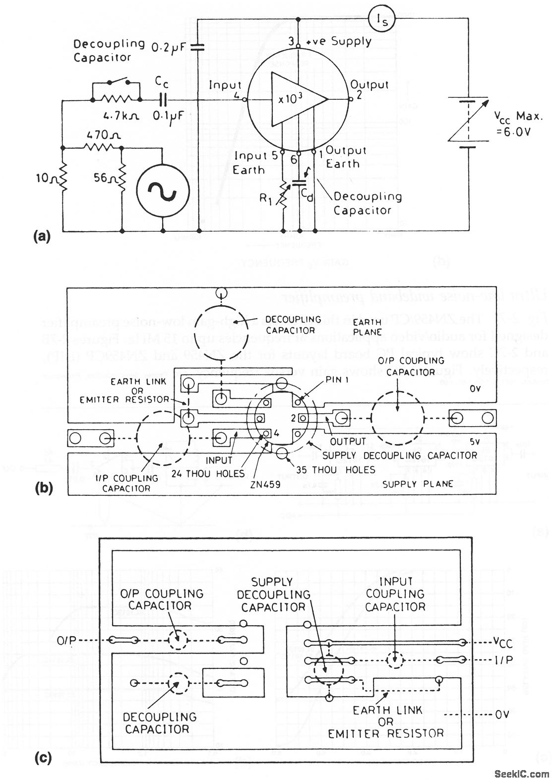
The ZN459/CP utilized in this circuit is a high-gain, low-noise preamplifier intended for audio and video applications at frequencies reaching up to 15 MHz. Figures 2-7B and 2-7C illustrate typical printed circuit board layouts for the ZN459 and ZN459CP...

These circuits are useful for video applications up to 10 MHz. The 3.3-pF capacitors serve as compensation capacitors. The capacitors connected to pins 7 and 4 act as bypass capacitors to prevent self-oscillations. Figure 76-18(a) illustrates a non-inverting configuration,...
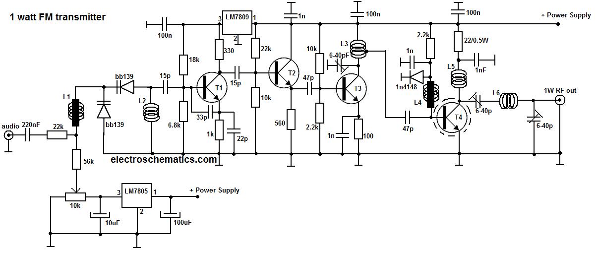
This portable FM transmitter features a limiter, a microphone amplifier, and PLL digital tuning, all integrated onto a single circuit board. The RF power output can be switched between 1 W (high) and 0.2 W (low). The schematic is...
This blog showcases various electronics circuit designs, applications, fields, and resources that can assist students, engineers, professionals, and anyone interested in electronics. For comments, suggestions, or inquiries about circuits, designs, or electronics designers, please contact [email protected]. The blog is...
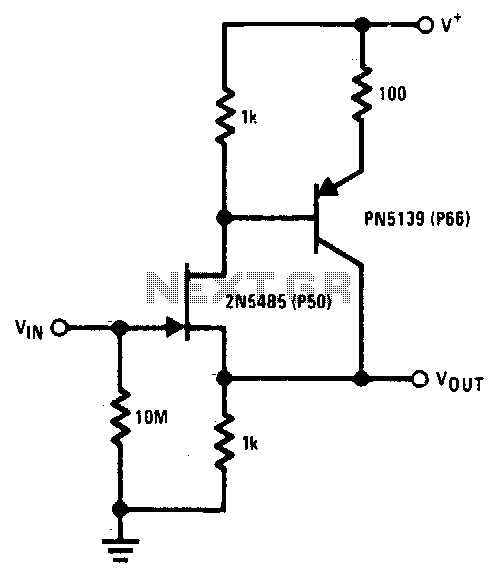
The 2N5485 features low input capacitance, making this compound series-feedback buffer a wide-band unity gain amplifier. The 2N5485 is a field-effect transistor (FET) that is often utilized in applications requiring low noise and high input impedance. Its low input capacitance...