
Wireless Coupled Scanning Voltmeter (ATMega8)
The power supply is the reference voltage in this case, and the binary-to-decimal conversion assumes that the reference voltage is +5 volts, so it is suggested that an adjustable regulator be used to obtain a precise +5 volts. Three alkaline cells (for example) could be used in series, but the calibration would be way off. Schematic of the 4 channel scanning voltmeter. The layout isn't critical. The 33 uH choke is used to reduce noise from the controller's VCC pin on the analog reference voltage.
The A/D converter setup and binary-to-decimal conversion routines were taken from the Low Cost Telemetry Device project on this site. The firmware was created by taking the Low Cost Telemetry Device firmware, removing the unneeded code, and adding calls to the Minimum Mass Wireless Coupler drivers instead of to the USART routines.
This circuit design incorporates a 10-bit analog-to-digital converter (ADC) based on the ATMega8 microcontroller, which serves as the core of the scanning voltmeter. The ADC is capable of converting input voltages into digital values, with a range determined by the reference voltage, which is typically set to +5V. To ensure accuracy in readings, an adjustable voltage regulator is recommended for generating the reference voltage, especially if using battery power.
The scanning voltmeter is designed to operate wirelessly, utilizing a Minimum Mass Wireless Coupler, allowing communication with a base unit located within a range of 10 to 15 cm. This feature enhances the versatility of the voltmeter, enabling it to be used in various applications without the constraints of wired connections. The circuit is intended to be simple and straightforward, making it accessible for demonstration purposes and educational projects.
In terms of circuit protection, it is essential to incorporate additional circuitry to safeguard the inputs from out-of-range signals, which could potentially damage the ADC. This may include clamping diodes or series resistors to limit the input voltage levels.
The schematic includes a 33 µH choke placed on the VCC pin of the microcontroller to filter out noise from the power supply, which could affect the accuracy of the analog reference voltage. The layout of the circuit is not critical, allowing for flexibility in design and implementation.
The firmware for the voltmeter is adapted from an existing Low Cost Telemetry Device project. It has been streamlined by removing unnecessary code and incorporating functions specific to the Minimum Mass Wireless Coupler, enabling efficient data transmission without reliance on USART communication. This optimization is vital for enhancing the performance of the scanning voltmeter in wireless applications.A 10 bit scanning voltmeter with a Minimum Mass Wireless Coupler, based on the ATMega8.Range to the Minimum Mass Base Unit is 10 to 15 cm. If the voltmeter is battery operated, it can be floated from ground. This project is very simple physically, intended to demonstrate how easily the Minimum Mass RF Link can be added to a project.
The circuit shown does not have a lot if the nice things that I would usually include in an instrument, such as the ability to handle out-of-range input signals without the circuit suffering damage. Therefore, I suggest that if you build this as a stand-alone instrument, that you add protection crcuitry to the inputs.
The basic Minimum Mass Wireless Coupler technology is described and links to other projects on this site that use the Minimum Mass Wireless Coupler are located on the web page, Minimum Mass Wireless Coupler. The power suuply is the reference voltage in this case, and the binary-to-decimal conversion assumes that the refernce voltage is +5 volts, so I sugges that an adjustable regulator be used to obtain a precise +5 volts. You could use three alkaline cells (for example) in series, but the calibration would be way off. Schematic of the 4 channel scanning voltmeter. The layout isn't critical. The 33 uH choke is reduce noise from the controller's VCC pin on the analog reference voltage. The A/D converter setup and binary-to-decmial conversion routines were taken from the Low Cost Telemetry Device project on this site.
The firmware was created by taking the Low Cost Telemetry Device firmware, removing the un-needed code, and adding calls to the Minimum Mass Wireless Coupler drivers instead of to the USART routines. 🔗 External reference
Related Circuits
A frequency meter can be utilized in speed sensors, tachometers, or any application that requires the measurement of repetitive signals. This frequency-to-voltage converter (FVC) is designed to facilitate the conversion process. The frequency meter is an essential instrument in various...
This is a JFET AC Coupled Integrator circuit. This circuit is used to achieve very high voltage gain. To achieve very high voltage gain, this circuit uses... The JFET AC Coupled Integrator circuit is designed to provide significant voltage amplification...
This is an easy-to-build yet highly accurate digital voltmeter designed as a panel meter. It can be utilized in DC power supplies or any application requiring precise voltage readings. The circuit uses the CL7107 Analog to Digital Converter (ADC)...
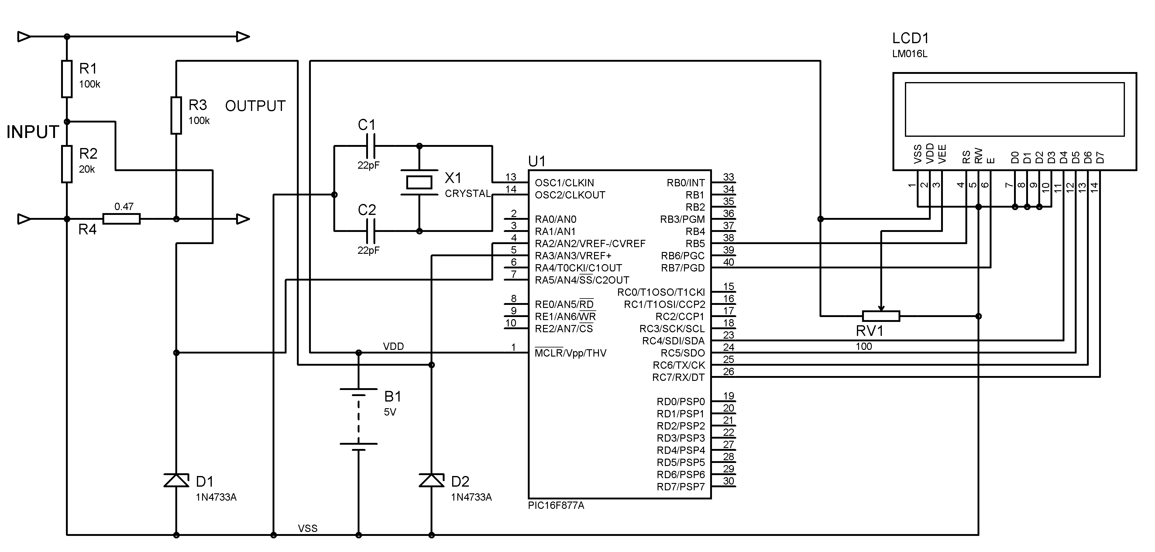
A voltmeter and ammeter can be constructed using a PIC microcontroller equipped with an Analog to Digital Converter (ADC). The project utilizes the PIC16F877A microcontroller, with results displayed on an LCD. This microcontroller is sufficient for testing purposes. For...
This system is designed to communicate or transmit a text message from one location to another using a wireless circuit. The text message is encrypted with a microcontroller, and the encrypted message is transmitted wirelessly. At the receiving end,...
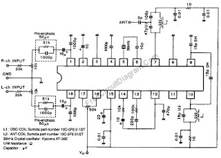
This wireless stereo FM transmitter is constructed using a monolithic integrated circuit (IC). The internal architecture of this FM transmitter IC includes a stereo modulator that generates a stereo composite signal, an FM modulator that modulates a carrier frequency...