
555 DC power supply circuit diagram of a protection device
The DC power supply protection circuit is designed to ensure safe operation of power supply systems by integrating several key components that work together to manage short-circuit conditions effectively. The buck rectifier power supply converts higher DC voltages to a stable lower voltage, which is essential for the operation of subsequent circuitry. The monostable delay circuit, utilizing the 555 timer, plays a critical role in monitoring the load conditions and providing a timed response to potential faults.
When the circuit experiences a short-circuit condition, the immediate response is to disengage the load to prevent damage to the power supply. The relay control circuit, activated by the 555 timer's output, ensures that the load is disconnected swiftly, minimizing the risk of overheating or failure. The audio feedback circuit serves as an additional layer of user notification, producing an audible signal that alerts operators to the fault condition, thereby prompting timely intervention.
The component values, particularly those of R3 and C4, are crucial as they define the delay time for the system's recovery from a fault condition. By adjusting these values, the protection circuit can be tailored to specific applications, allowing for flexibility in various power supply designs. The auto-recovery feature enhances the usability of the circuit, as it automatically reconnects the load once the fault condition is resolved, ensuring minimal downtime.
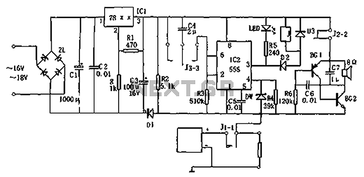
In summary, this DC power supply protection circuit is an essential component for safeguarding power systems, providing a reliable mechanism for fault detection, load disconnection, and user notification, all while allowing for customizable protection parameters. Circuit diagram for the DC power supply protection circuit. The device consists of buck rectifier power supply, monostable delay circuit, relay control circuit, audio feedback oscillation circuit. The entire circuit DC voltage Vdd, and Vdd where the buck rectifier power supply is + (5 ~ 12) V, depending on the value of specific VDD regulator block IC1 may be. Monostable delay circuit consists of IC2 (555) and R3, C4 and other components. Usually, normally closed contact J1-1 is closed, so that the potential of pin IC2 normal load is high (1V above), when the load is short-circuited due to 555 feet potential is low ( 0.6V) and is forced to reset output pin low J pull the relay contacts J1-1 off, cut off the short-circuit load.
Meanwhile contacts J2-2, J3-3 respectively connected, so that the audio feedback oscillator BG1, BG2, C6, C7, R6 and composition by applying a voltage oscillation, which issued about lkHz acoustic signal to alert the use to pay attention. After contact J3-3 switched, C4 is charged through R3 so IC potential drop foot, when the potential of pin falls below 1/3VDD, 555 occurs is set.
high output enable pin J release, contact J1-1 connected. If this time is still short-circuited, then protected. C4 of the respective charging time is 555 delay guard time td 1.1R3C4. Protection time can be adjusted by changing the time constant R3C4. The protection circuit may short-circuit protection DC voltage source, which can be used as an annex to the voltage source, or any power supply design, integrated design. Its l.5 ~ 50V DC output voltage in the range of source in the event of a short circuit at a speed of 0.1 seconds to switch the load, for protection, and this delay circuit also has auto-recovery function.
Related Circuits
The sound produced mimics the rise and fall of an American police siren. When first powered on, the 10µF capacitor is discharged, and both transistors remain off. Upon pressing the push button switch, the 10µF capacitor begins to charge...
The charger operates with a charging voltage of 2.4 V per cell, aligning with the recommendations of most manufacturers. The circuit delivers a charging voltage of 14.4 V (6 cells at 2.4 V per cell) in a pulsed manner...
Application circuit using three stereo digital potentiometers to control volume, balance, and fader in a four-speaker configuration with a push-button interface. The application circuit utilizes three stereo digital potentiometers, which are essential components for managing audio levels in a multi-speaker...
This circuit is a musical doorbell. When the button S1 is pressed, a short melody plays. If the button is pressed multiple times in quick succession or held down, a different melody is generated, and the melody plays for...
This is a portable, high-power incandescent electric lamp flasher. It functions as a dual flasher (alternating blinker) capable of managing two independent 230V AC loads (bulbs L1 and L2). The circuit is entirely transistorized and operates on battery power....
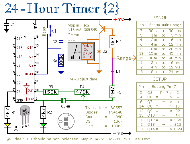
These two circuits are multi-range timers that offer periods of up to 24 hours and beyond. They can function as repeating timers or single-shot timers. Both circuits are fundamentally the same, with the primary distinction being their behavior in...
Warning: include(partials/cookie-banner.php): Failed to open stream: Permission denied in /var/www/html/nextgr/view-circuit.php on line 713
Warning: include(): Failed opening 'partials/cookie-banner.php' for inclusion (include_path='.:/usr/share/php') in /var/www/html/nextgr/view-circuit.php on line 713