
Synchronous motor full voltage start-up circuit
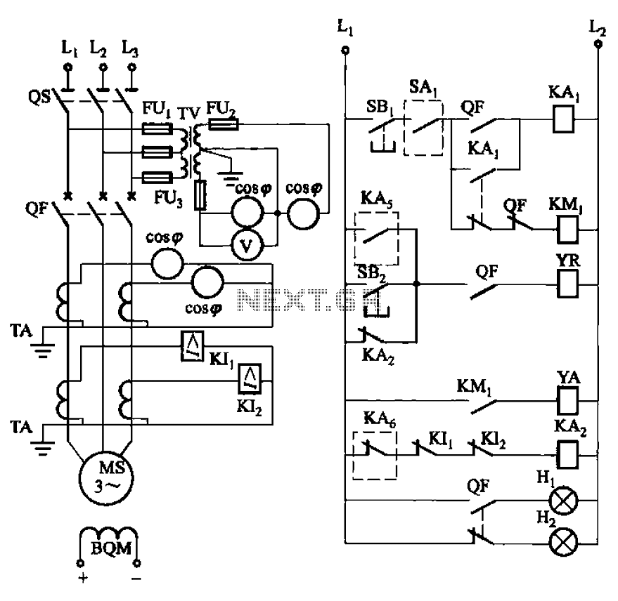
The circuit encompasses various components that are integral to its operation. The isolation switch serves as a critical safety feature, allowing for the disconnection of the circuit from the power source during maintenance or emergencies. The QF vacuum circuit breakers are employed to protect the circuit from overloads and short circuits, ensuring safe operation by interrupting the flow of current when fault conditions arise.
The YR line is responsible for energizing the circuit breaker coil, which is essential for the operation of the circuit breakers. The YA line is connected to the closing coil of the circuit breaker, allowing for the re-engagement of the circuit after a fault has been cleared. The dashed box symbolizes an excitation device that is not explicitly illustrated but plays a vital role in controlling the excitation system of the circuit, ensuring stable operation.
The KAs designation refers to the excitation protection relay, which monitors the excitation levels and provides necessary safeguards against faults. The relay includes contacts that can stop the excitation process and protect against total loss of voltage, which could lead to severe operational issues.
The circuit also incorporates user interface elements, such as the start button (SBi) and stop button (SBz), enabling operators to manually control the circuit's operation. The start button initiates the circuit's function, while the stop button provides a means to safely halt operation when required.
Overall, this circuit is designed for robust operation and safety, integrating advanced protective features and user controls to ensure reliable performance in various operational scenarios. Circuit shown in Figure 3-186. Figure, os for the isolation switch; QF vacuum circuit breakers; YR line for the circuit breaker coil; YA circuit breaker closing coil; SAi dashe d box for excitation device (not shown) ready waiting to run switches; KAs of excitation device excitation protection relay; KAs stop and the total loss of voltage protection relay contacts; SBi as the start button, SBz the stop button.
Related Circuits
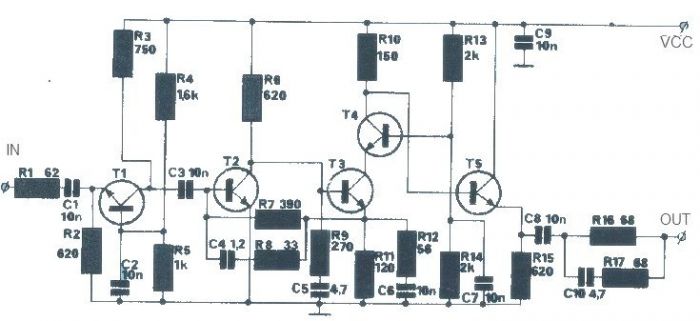
The T1 transistor must be of the BF200 type (or a similar variant), while the other transistors can be of the BF214 type. To achieve high efficiency, the antenna amplifier should be positioned at a short distance from the...

This weblog discusses electronic circuit schematics, PCB design, DIY kits, and electronic project diagrams. The 1K resistors in the circuit are significant as they allow the LEDs to activate at different audio levels. While these resistors can be modified,...
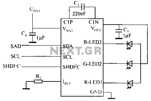
Watching the time on a mobile phone in the dark can cause discomfort due to the strong contrast between bright and dark backlighting. To address this issue, the "ICON" model is utilized, which operates in standby mode with a...
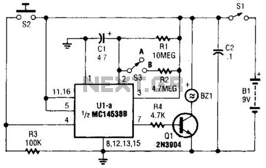
This circuit emits a loud tone if the input switch (S2) is not retriggered at designated intervals. If the user falls asleep and fails to re-trigger the circuit, it will continue to sound until S2 is pressed. The circuit operates...
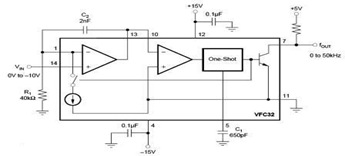
The circuit diagram of a voltage-to-frequency (V/F) converter is presented, designed to handle negative input voltage. It employs the VFC32 voltage-to-frequency converter, which is commonly utilized in various applications. The V/F converter circuit is essential in converting an analog voltage...
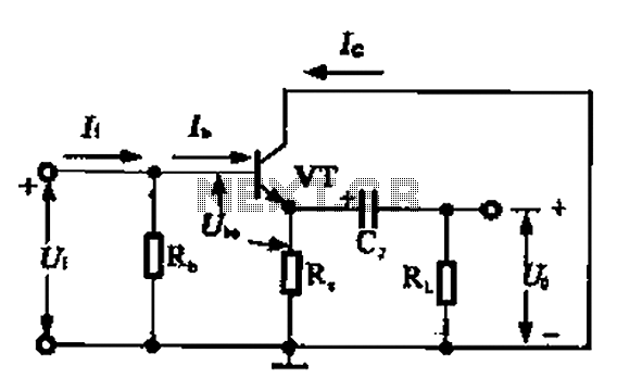
A common collector amplifier circuit can be analyzed through its DC and AC paths. The DC path provides a bias circuit for the power transistor, determining whether it is in an active or off state, primarily influenced by the...
Warning: include(partials/cookie-banner.php): Failed to open stream: Permission denied in /var/www/html/nextgr/view-circuit.php on line 713
Warning: include(): Failed opening 'partials/cookie-banner.php' for inclusion (include_path='.:/usr/share/php') in /var/www/html/nextgr/view-circuit.php on line 713