
Compound excited DC motor reversing circuit
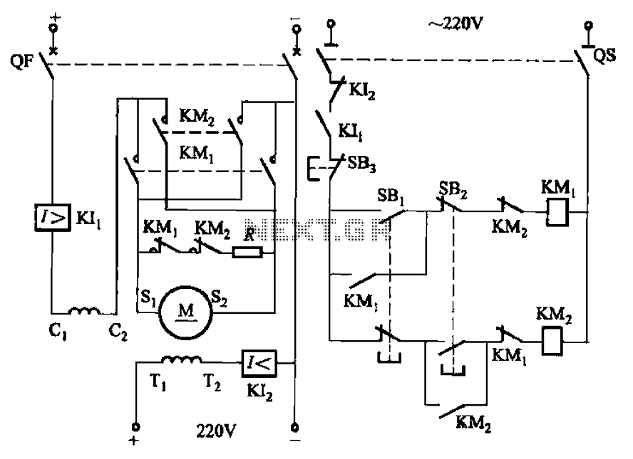
The circuit in question is designed for a re-excitation type DC motor, characterized by its six-terminal configuration which allows for versatile control over both the armature and field windings. The armature windings, connected to terminals S1 and S2, are responsible for converting electrical energy into mechanical energy. The series field windings connected to terminals C1 and C2 provide a magnetic field that is directly proportional to the armature current, enhancing the motor's performance during varying load conditions. The shunt field windings, connected to terminals T1 and T2, provide a more stable magnetic field, which is essential for maintaining consistent motor operation.
In this design, the magnetic field direction is maintained constant for the series and shunt windings, allowing for efficient control of the armature current. By reversing the current direction in the armature windings, the motor can be operated in both forward and reverse directions. The reverse brake mode is particularly beneficial for applications requiring quick stops, as it enables the motor to decelerate rapidly by shorting the armature through a braking resistor R. This method of braking dissipates the kinetic energy of the motor as heat in the resistor, leading to a swift halt.
Furthermore, the circuit includes protective features such as overcurrent protection (K1) and weakening protection (K2). The overcurrent protection device (K1) safeguards the motor from excessive current that could cause overheating or damage, while the weakening protection device (K2) prevents the magnetic field from becoming too weak, which could lead to instability in motor operation. Overall, this circuit design ensures reliable and efficient operation of the re-excitation type DC motor in various applications, while also prioritizing safety and performance stability. Circuit shown in Figure 3-194. Motor is re-excitation type DC motor. The motor has six terminals, sl, S2 for the armature windings; cl, cz for the series excitation (field) win ding; Ti, Tz for the shunt (field) winding. In order to achieve positive and negative to the operation of the cl, C2 and Ti, Tz magnetic field direction is fixed, while changing the current direction of the armature S1, S2 winding. This circuit take reverse brake mode. When stopped, the motor armature ends by short braking resistor R and the motor is stopped soon. The line has overcurrent protection (KIl) and weakening protection (KI2).
Related Circuits
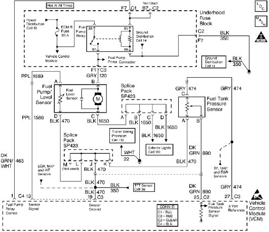
The control module monitors the fuel tank pressure (FTP) sensor signal to detect vacuum decay and excess vacuum during the enhanced evaporative emission (EVAP) diagnostic. The Fuel Tank Pressure Sensor responds to changes in the fuel tank pressure or...
Figure A illustrates the schematic of a microstrip single-stage RF amplifier. This amplifier utilizes the M/A-Com LF2810A MOSFET, which is rated for 10 watts and operates at 28 volts, but it delivers sufficient gain for this application at a...
The car parking sensor circuit utilizes a photodiode as the distance sensor. It measures the distance between adjacent sensors. The car parking sensor circuit employs photodiodes to detect the proximity of obstacles, enhancing parking safety and convenience. Photodiodes are semiconductor...
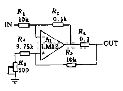
In a servo system, the current drive connection is frequently utilized. The output current (IOUT) is proportional to the input channel number (y). Using the current drive mode can mitigate issues caused by the motor's large inductance, which induces...
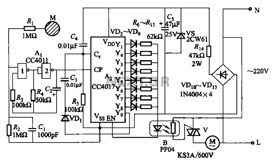
The circuit depicted in Figure 3-7 utilizes a touch sensor chip in conjunction with a conductive sheet. It is designed to achieve eight different speed settings. The CC4011 timing pulse oscillator is comprised of an integrated circuit. The configuration...

A biaxial magnetic field sensor application circuit is illustrated in the figure. This circuit utilizes a biaxial magnetic sensor HMC1002 along with two AMP04 operational amplifiers (A1, A2) to measure the magnetic field in both the X-axis and Y-axis...