
0-24v digital variable power supply circuit

The circuit operates by utilizing a PIC microcontroller as the central control unit, which manages the output voltage and current levels based on user input. The microcontroller interfaces with an analog-to-digital converter (ADC) to monitor the output voltage and current, ensuring accurate readings displayed on the LCD. The LCD is connected via an appropriate communication protocol, such as I2C or SPI, allowing for efficient data transfer and display updates.
The power supply features a voltage regulator circuit, which may include components such as operational amplifiers, MOSFETs, or linear regulators to achieve the desired output characteristics. The push-button switch is connected to the microcontroller's GPIO pins, enabling the user to increment or decrement the output voltage and current. Debouncing techniques may be implemented in the software to ensure stable readings during adjustments.
Additional components may include protection diodes to prevent back EMF, capacitors for filtering noise, and resistors for setting reference voltages. The design may also incorporate thermal management features to prevent overheating during operation, ensuring reliability and longevity of the power supply.
This variable power supply circuit is suitable for various applications, including laboratory experiments, testing electronic devices, and powering prototype circuits. Its digital interface provides a user-friendly experience, allowing for precise adjustments and monitoring of output parameters.The following circuit diagram is a variable power supply which controlled by PIC microcontroller. The LCD display is used to showing the actual value of output current voltage. This is a digital power supply, use the push on switch to adjust the output voltage and current value. 🔗 External reference
Related Circuits
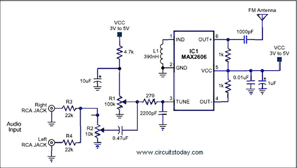
A simple single-chip FM transmitter circuit with a diagram and schematic using the IC MAX 2606, which is a high-performance voltage-controlled oscillator (VCO). The FM transmitter circuit utilizing the MAX 2606 is designed for efficient frequency modulation of audio signals....
This circuit allows for amplifier volume control without the need for a potentiometer, utilizing an IC DS1669. The operating voltage for this type of IC ranges from 4.5 volts to 8 volts; however, in this circuit, it is used...
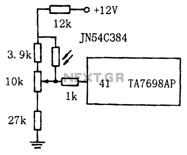
The circuit for automatic brightness adjustment in a television utilizes a photosensitive resistor and a contrast potentiometer connected to an intermediate stage. The photosensitive resistor varies its resistance based on light intensity, causing changes in the potential at the...
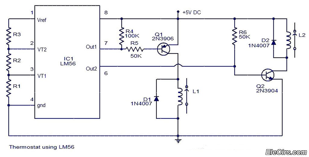
The LM56 Thermostat Project Circuit Diagram includes a schematic for the LM56 thermostat. The values of resistors R1, R2, and R3, which determine the required trip points VT1 and VT2, can be calculated using the following equations: VT1 =...
The integrated circuit LA3607 enables the configuration of a 7-band graphic equalizer for a single audio channel by incorporating additional capacitors and variable resistors. The cutoff frequency can be modified using variable resistors. It demonstrates high stability when handling...
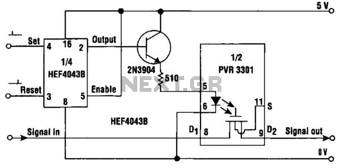
This simple circuit provides a solid-state equivalent of the electromechanical latching relay. The switching mechanism is clean, highly resistant to vibration and shock, and is not sensitive to magnetic fields or position. The circuit operates as follows: a set...