
0-30V Lab Variable Power Supply
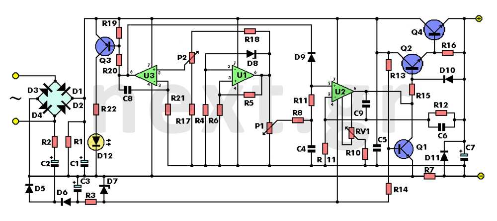
The circuit functions as follows: The output voltage of U1 increases until D8 starts conducting, stabilizing the circuit and establishing a reference voltage of 5.6V across R5. The current through the non-inverting input of the operational amplifier is negligible, meaning all current through R5 also flows through R6, resulting in the output voltage of U1 being twice the diode voltage.
U2, using resistors R11 and R12, amplifies the voltage according to the formula A = (R11 + R12) / R11, raising the voltage to approximately 20V. The RV1 trimmer and resistor R10 are utilized to set the output voltage limits, allowing it to be adjusted down to zero.
When the power supply operates with a load connected to its output, all output current passes through resistor R7. At this point, the inverting input of U3 has a potential of 0V and is biased by resistor R21, while the non-inverting input of U3 is biased by a small voltage that varies from 0 to 2V, depending on the position of potentiometer P2. If the voltage at this point is 1V and the output voltage is set to a few volts, an increase in load will raise the voltage across R7, activating U3. This, in turn, controls U2 via D9, allowing U2 to be regulated by a specific voltage value.
From this moment, the output current limiting circuit is engaged, with U3 managing U2 to maintain a constant voltage drop across R7. Capacitor C8 ensures stability in the U3 feedback loop.
As long as the power supply delivers a constant voltage, LED D12 remains off. However, if the current exceeds the preset value indicated by P2, the LED illuminates, indicating that the power supply is functioning as a constant current source while simultaneously adjusting the output voltage to maintain a constant current for the load.
Resistors R19 and R20 define the operating conditions of Q3, which detects when the current limiting circuit is activated, causing LED D12 to light up through R22, which sets the operating current for the LEDs. The current limitation is controlled by R7, which acts as a transducer, with the current limit value adjustable via potentiometer P2. Thus, the voltage at each end of R7 varies based on the position of P2, divided by the internal reference voltage of integrated circuit U1.
The junctions of D2, D4, R2, and diodes D5, D6, along with capacitors C2, C3, and resistor R3, generate a negative voltage necessary for the operation of U2 and U3, allowing them to reach 0V. Diode D7 stabilizes the negative voltage supplied to terminals 4 of U2 and U3.
Resistor R4 ensures proper polarity for U1, while capacitors C4 and C5 filter out high frequencies that could destabilize the integrated circuits.
Transistor Q1 safeguards the power supply from negative voltage drops occurring when the power supply ON-OFF switch is engaged, maintaining a low output from U2.
Resistor R14 disables the transistor when the power supply is functioning normally, allowing for quick voltage reduction without waiting for capacitor discharge, thus saving time.
Finally, via R15, voltage is directed to transistors Q2 and Q4, which provide the required power of 0.5A. Resistor R16 polarizes transistors Q2 and Q4, which are configured in a Darlington pair.
Components List
Resistors
- R1 = 2.2 KΩ 1W
- R7 = 0.47Ω 5W Brick
- R2 = 82Ω 1/4W
- R3 = 220Ω 1/4W
- R4 = 4.7KΩ 1/4W
- R5, R6, R13, R20, R21 = 10KΩ 1/4W
- R8, R11 = 27KΩ 1/4W
- R9, R19 = 2.2KΩ 1/4W
- R10 = 270KΩ 1/4W
- R12, R18 = 56KΩ 1/4W
- R14 = 1.5KΩ 1/4W
- R15, R16 = 1KΩ 1/4W
- R17 = 33Ω 1/4W
- R22 = 3.9KΩ 1/4W
- RV1 = 1MΩ Trimmer
- P1, P2 = 10KΩ Linear Potentiometer
Capacitors
- C1 = 3300μF/40V Electrolytic
- C2, C3 = 47μF/63V Electrolytic
- C4 = 100nF Polyester
- C5 = 220nF Polyester
- C6 = 100pF Ceramic
- C7 = 10μF/50V Electrolytic
- C8 = 330pF Ceramic
Transistors
- Q1 = BC547 NPN Transistor
- Q2 = 2N2219 NPN Transistor
- Q3 = BC327 PNP Transistor
- Q4 = BD249C NPN Power transistor
Diodes
- D1, D2, D3, D4 = 1N5402
- D5, D6 = 1N4148
- D7, D8 = 5.6V Zener
- D9, D10 = 1N4148
- D11 = 1N4001
- D12 = LED
Operational Amplifier ICs
- U1, U2, U3 = TL081
Transformer
- T1 = 220V - 18V/3AAt the left side (input AC) goes the secondary of a 220 volt (primary) 18 Volt (secondary) / 3 Ampere mains transformer. The alternating voltage of 18 volts from its secondary transformer is rectified by the diodes D1, D2, D3 and D4, which are connected to a bridge arrangement and make a double rectifier.
The pulse from the bridge exit is applied to the ends of the R1-C1 net and filtered. The circuit around the integrated U1 produces the necessary reference voltage for the stable operation of the circuit. The Zener D8 diode operates at the minimum current for zero thermal coefficient to ensure stable operation of the power supply.
The resistors R5 and R6 regulate the output of the reference generator.
The circuit works as follows:
The voltage at the output of U1 increases until the D8 starts running, the circuit stabilizes and the reference voltage of the Zener (5.6 Volt) is shown at the ends of R5. The current flowing through the non-inverting input of the effector amplifier is negligible, so all current flowing through R5 also passes through R6 and so the output voltage of U1 is twice the diode voltage.
U2, by means of the resistors R11 and R12, increases the voltage according to the formula A = R11 + R12 / R11, thus increasing the voltage to approximately 20 volts.
The RV1 trimmer and resistor R10 are used to set the output voltage limits to go down to zero.
When the power supply is in operation and a load is connected to its output, then all output current passes through resistor R7. At this point, the reversible input (-) of U3 has a potential of 0 and is polarized by the resistor R21 while the non-inverting (+) input of U3 is polarized by a small voltage ranging from 0 - 2 volts depending on the position of the rotor Potentiometer P2.
Suppose the voltage at this point of the circuit is 1 volt and the output voltage is set to a few volts. If the load increases then the voltage at the ends of R7 will increase, so U3 will be activated, and it will lead U2 through the D9 passage, and consequently the U2 is controlled by a voltage value and above.
From this moment, the output current limiting circuit acts, since U3 controls the operation of U2 so that the voltage drop across the edges of R7 is constant.
C8 capacitor provides the U3 reconnection loop required stability.
As long as the power supply works and provides constant voltage, LED D12 is off. While the current exceeds the preset by P2 value, the LED lights up and the power supply from a constant voltage source is a constant current source and at the same time the output voltage is changed so as to keep the current constant for that load.

R19, R20 defines the necessary operating conditions of Q3 that detects when the current limiting current circuit starts and operates at that moment and LED D12 lights up via the R22 that defines the operating current of the LEDs.
However, the current limitation is made by the R7 that serves as a transducer, and the current value of the limit circuit is set by the potentiometer P2. Thus, depending on the position of the potentiometer P2, a different voltage occurs at each end of the R7, and is divided by the internal reference voltage of the integrated circuit U1.
From the junction of D2, D4, through R2 and the D5, D6, C2, C3, R3, produces a negative voltage necessary for the operation of U2, U3 so that they can go down to 0 volts.
D7 diode stabilizes The negative voltage caused to terminals 4 of U2 and U3.
Resistor R4 ensures polarity at U1 and capacitors C4 and C5 release the circuit from high frequencies that could cause instability in the integrated circuits.
Transistor Q1 protects the power supply from the negative voltage drop caused when the power supply ON-OFF switch is closed, keeping the output of U2 low.
Resistor R14 cuts off the transistor when the power supply is working normally, and in this simple way the power supply is very useful for experimentation because it drastically cuts the output voltage without having to wait until the capacitor unloads, thus losing plenty of time.
Finally, via R15 the voltage is fed to the transistors Q2 and Q4 which provide the required power of 0.5 A. The resistor R16 finally polarizes the transistors Q2 and Q4, which are in DARLINGTON.

Components List
| Resistors | Capacitors | Transistors |
| R1 = 2.2 KΩ 1W R7 = 0.47Ω 5W Brick R2 = 82Ω 1/4W R3 = 220Ω 1/4W R4 = 4.7KΩ 1/4W R5,R6,R13,R20,R21 = 10KΩ 1/4W R8,R11 = 27KΩ 1/4W R9,R19 = 2.2KΩ 1/4W R10 = 270KΩ 1/4W R12,R18 = 56KΩ 1/4W R14 = 1.5KΩ 1/4W R15, R16 = 1KΩ 1/4W R17 = 33Ω 1/4W R22 = 3.9KΩ 1/4W RV1 = 1MΩ Trimmer P1,P2 = 10KΩ Linear Potentiometer |
C1 = 3300μF/40V Electrolytic C2,C3 = 47μF/63V Electrolytic C4 = 100nF Polyester C5 = 220nF Polyester C6 = 100pF Ceramic C7 = 10μF/50V Electrolytic C8 = 330pF Ceramic |
Q1 = BC547 NPN Transistor O2 = 2N2219 NPN Transistor Q3 = BC327 PNP Transistor Q4 = BD249C NPN Power transistor |
| Diodes | Operational Amplifier ICs | |
| D1,D2,D3,D4 = 1N5402 D5,D6 = 1N4148 D7,D8 = 5.6V Zener D9,D10 = 1N4148 D11 = 1N4001 D12 = LED |
U1,U2,U3 = TL081
|
|
| Transformer | ||
|
T1 = 220V - 18V/3A
|
Related Circuits
The first schematic is designed for individuals who exclusively purchase electronic components from Radio Shack. It allows for a straightforward shopping experience, enabling one to acquire all necessary parts in-store. For the heat sink, it is recommended to visit...
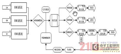
Currently, the switching power supply boasts high performance with an efficiency of 75%. The efficiency of single-scale integration switching power supplies has exceeded 90%. This advancement addresses energy concerns and enhances the performance of numerous energy-saving electrical devices. The...
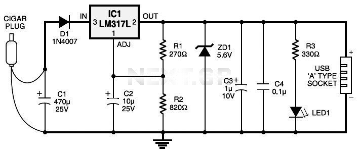
Currently, nearly all computer systems include logic blocks designed for interfacing with a USB port. In practical terms, a USB port can provide more than 100 mA of continuous electric current at 5V to the peripherals connected to the...
This instructable demonstrates how to create low-power wireless charging circuits that facilitate the transfer of energy without direct electrical connections. Wireless charging circuits utilize electromagnetic induction to transfer energy between two coils, typically referred to as the transmitter and receiver...
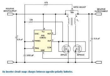
To transfer charge in either direction between unevenly loaded positive and negative battery buses, an inverting DC transformer is required. One implementation is the symmetrical flyback converter, which can produce a negative output from a positive supply or a...
Construct a low-cost and relatively simple robot that activates whenever a desk lamp is illuminated. The design does not incorporate any sensors. This robot can be designed using basic electronic components to create a simple activation mechanism based on light...
Warning: include(partials/cookie-banner.php): Failed to open stream: Permission denied in /var/www/html/nextgr/view-circuit.php on line 713
Warning: include(): Failed opening 'partials/cookie-banner.php' for inclusion (include_path='.:/usr/share/php') in /var/www/html/nextgr/view-circuit.php on line 713