
1.2Ghz-frequency-counter
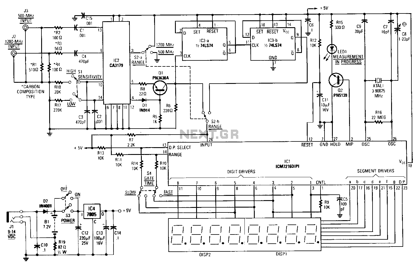
The output of the CA3179 is fed through the D1Q1 circuit. These components serve to boost the 1V output of the CA3179 to a standard TTL level. Depending on the position of range switch S2b, the signal is passed directly to the 7216 or through a divide-by-four circuit built from the two D flip-flops in IC3. The other half of the range switch S2a controls the voltage at pin 3 of the CA3179. When pin 3 is high, the signal applied to pin 9 is fed through an additional internal divide-by-four stage before being amplified and output on pins 4 and 5. When pin 3 is low, the signal on pin 13 is processed for output without internal division. A 3.90625 MHz crystal provides the time base, yielding a fast gate time of 0.256 seconds. The displayed frequency equals the input frequency divided by 1000 in fast mode. In slow mode, the gate time is 2.56 seconds, and the displayed frequency equals the input frequency divided by 100. Switch S4, gate time, performs two functions: it selects the appropriate gate time according to which digit output of IC1 the range input is connected to, and it controls another input of the 7216: the decimal point select input. The decimal point of the digit output to which that pin is connected will illuminate, providing a reading in MHz.
The circuit described integrates several key components for frequency measurement and signal processing. The CA3179 serves as a voltage reference and signal conditioner, outputting a 1V signal that is subsequently boosted to a TTL level by the D1Q1 circuit. This ensures compatibility with digital logic levels required by subsequent components.
The range switch S2b plays a crucial role in determining the path of the signal. When engaged, it allows the signal to either bypass the divide-by-four circuit, facilitating direct input to the 7216, or to pass through the IC3 flip-flops, which further manipulate the signal for specific measurement applications. This flexibility is essential for accommodating various input frequency ranges.
The second part of the range switch, S2a, adjusts the voltage at pin 3 of the CA3179. The state of pin 3 directly influences the processing of the signal. When pin 3 is high, the signal from pin 9 undergoes an additional division, effectively reducing the frequency for amplification and output on pins 4 and 5. Conversely, when pin 3 is low, the signal at pin 13 is outputted directly, maintaining the integrity of the input frequency without division.
The timing aspect of the circuit is governed by a 3.90625 MHz crystal oscillator, which establishes a precise time base for frequency measurements. The fast mode operation, with a gate time of 0.256 seconds, allows for rapid frequency readings, while the slow mode extends the gate time to 2.56 seconds for more stable measurements. The division factors of 1000 and 100 in fast and slow modes, respectively, ensure that the output frequency is appropriately scaled for display.
Switch S4 is pivotal in managing the display output. It not only selects the gate time corresponding to the digit output of IC1 but also controls the decimal point select input of the 7216. This feature ensures that the correct decimal point lights up, providing clear and accurate frequency readings in megahertz, enhancing user interpretation of the measurement data.The output of the CA3179 is fed through the Dl!Q1 circuit. Those components serve to boost the 1-V output of the CA3179 to a standard TTL level. Then, depending on the position of range switch S2b, the signal is passed directly to the 7216, or through the divide-by-four circuit built from the two D flip-flops in IC3. The other half of the range switch S2a controls the voltage at pin 3 of the CA3179. When pin 3 is high, the signal applied to pin 9 is fed through an extra internal divide-by-four stage before it is amplified and output on pins 4 and 5.
When pin 3 is low, the signal on pin 13 is simply processed for output without being divided intemally. A 3.90625-MHz crystal provides the time base; the crystal yields a fast gate time of 0.256 second. The displayed frequency equals the input frequency divided by 1000 in the fast mode. In slow mode, gate time is 2.56 seconds. The displayed frequency equals the input frequency divided by 100 in the slow mode. Switch S4, gate time, performs two functions. First it selects the appropriate gate time according to which digit output of IC1 the range input is connected to.
Another of the 7216"s inputs is also controlled by S4: the dp select input. The decimal point of the digit output to which that pin is connected will be the one that lights up. The correct decimal point illuminates, according to the position of S4, to provide a reading in MHz.
🔗 External reference