
1.57-GHz Front-End for GPS Receiver
The Global Positioning System (GPS) operates through a constellation of 24 satellites positioned in six orbital planes, each at an altitude of 20,200 kilometers. These satellites are arranged such that they complete an orbit around the Earth every 12 hours, with each orbital plane inclined at an angle of 55 degrees to the equator. Each plane contains four satellites, ensuring that at least four satellites are visible from any point on the Earth's surface at any given time, which is essential for accurate positioning.
GPS positioning relies on a technique known as one-way time-of-arrival ranging. Each satellite broadcasts signals that include universal time (UTC) and navigation data using a spread spectrum code division multiple access (CDMA) technique. A GPS receiver determines its position and velocity by measuring the time it takes for signals from at least four satellites to reach it. This information is then combined with orbital correction data transmitted by the satellites to enhance accuracy.
The GPS system provides two distinct services: the Precise Positioning Service (P-code), which is reserved for military use, and the Standard Positioning Service (C/A-code), which is accessible to the general public. Both services utilize two primary frequencies: L1, which operates at 1575.42 MHz and carries the C/A-code, and L2, which operates at 1227.6 MHz and carries the P-code. These frequencies are derived from a 10.23 MHz atomic frequency standard, ensuring precise timing and synchronization.
To mitigate interference between the signals from different satellites, GPS employs pseudorandom noise codes that exhibit low cross-correlation, making it easier for receivers to distinguish between signals. The C/A-code, specifically, utilizes a sequence of 1023 chips structured as Gold codes, which further aids in reducing signal interference.
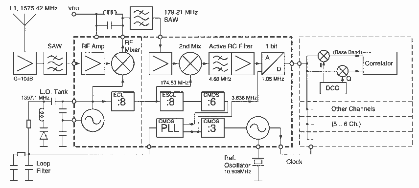
The design of a low-power RF front-end integrated circuit for GPS receivers, particularly targeting the 1575.42 MHz civilian L1 band, is crucial for applications in portable consumer electronics. Such integrated circuits are intended to provide a GPS time reference, facilitating accurate time zone settings for wearable devices. Given the constraints of power consumption, a small lithium battery supplying between 2.4 to 3.5 volts is specified as the power source. Additionally, considerations regarding the number and size of external components are critical, as they impact both the overall cost and the physical space available in compact designs. These factors must be carefully addressed in the planning and development stages of the system to ensure optimal performance and user satisfaction.The GPS is based on 24 satellites located in six orbital planes at a height of 20 200 km and circle the Earth every 12 h. Each plane is inclined at 55 to the Earth’s equator and contains four satellites. The GPS positioning is based on oneway time-of-arrival ranging. Each satellite sends the universial time (UTC) and navigation data using a spread spectrum code division multiple access (CDMA) technique.
A receiver can calculate its own position and speed by correlating the signal delays from any four satellites and combining the result with orbit-correction data sent by the satellites. Two services are provided by GPS: a precise positioning service (P-code) whose use is restricted to military and a standard positioning service (coarse acquisition, C/A-code), less precise than the P-code but available to everyone. All 24 satellites send on the same two frequencies: L1 is the primary frequency and carries the C/A-code, and L2 is the secondary frequency and carries the P-code.
The two frequencies are derived from a 10.23-MHz atomic frequency standard. The frequency of L1 is 1575.42 MHz (154 times the atomic clock) and that of L2 is 1227.6 MHz (120 times the atomic clock). Interference between signals of different satellites is avoided using pseudorandom signals with low cross-correlation for the CDMA modulation.
The C/A-code uses 1023 chips Gold codes [2], [3]. The integrated circuit reported in this work is a low-power RF front-end for a GPS receiver for the 1575.42 MHz civilian L1 band. The immediate application of such an integrated receiver is to provide GPS time reference—GPS positioning will be used to set the correct time zone—for small, portable (wearable) consumer products.
Low power consumption is therefore a primary requirement, and the speci?ed power source is a small lithium battery (2.43.5 V). The number and size of external components are also important requirements, not only due to cost, but also the space available.
Both requirements must already be addressed during system planning. 🔗 External reference
Related Circuits
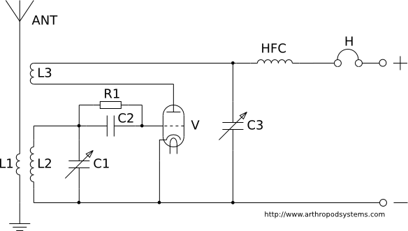
This page discusses various regenerative receiver circuits that were utilized primarily between the 1920s and 1940s. The connections are illustrated using electron tubes (vacuum tubes or valves), although FET transistors can be substituted with minimal adjustments. For radio enthusiasts,...
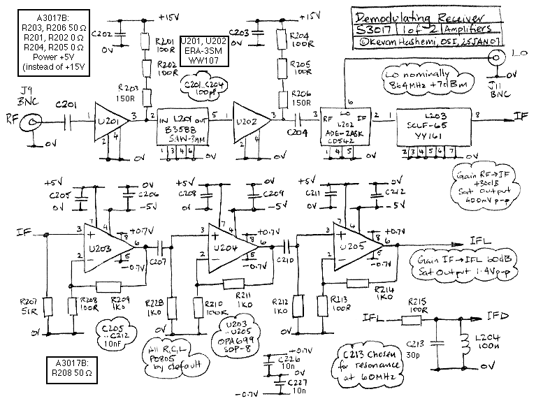
The Demodulating Receiver (A3017) features a 902 to 930 MHz 30-dB amplifier, a downshifter, a 60-dB 50-MHz limiting IF amplifier, a frequency discriminator, and an amplitude demodulator. The A301701A circuit board also includes additional copies of the A3016SO SAW...
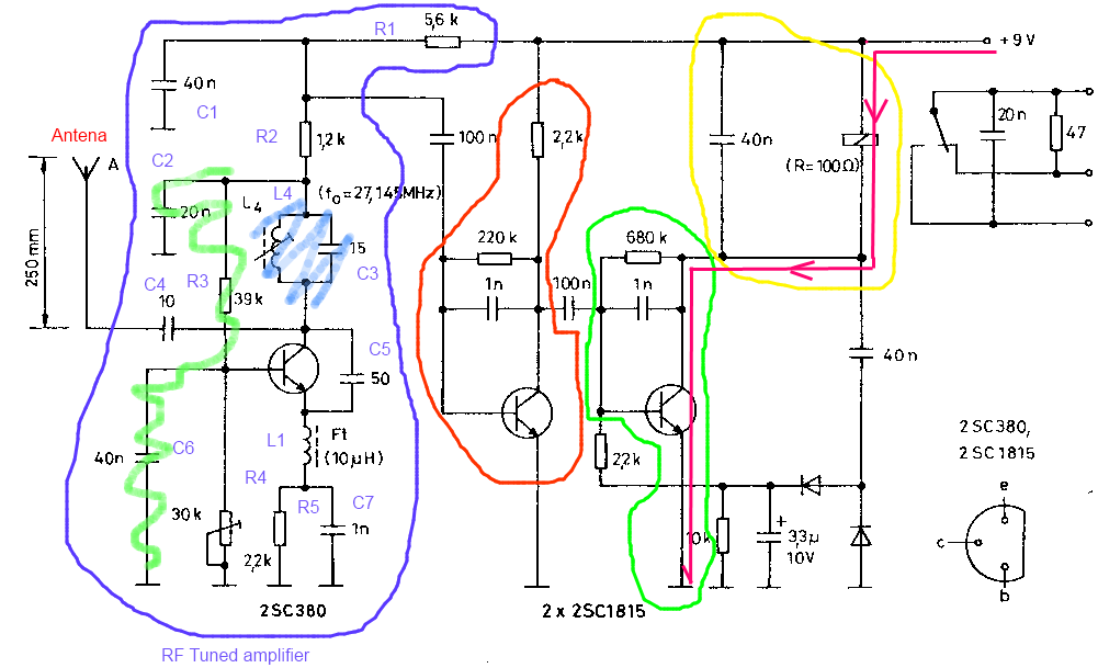
The circuit described is a toy car receiver, which operates similarly to the transmitter but in reverse and with additional filtering. The receiver is tuned to a frequency of 27.145 MHz to capture signals at this frequency. Following the...
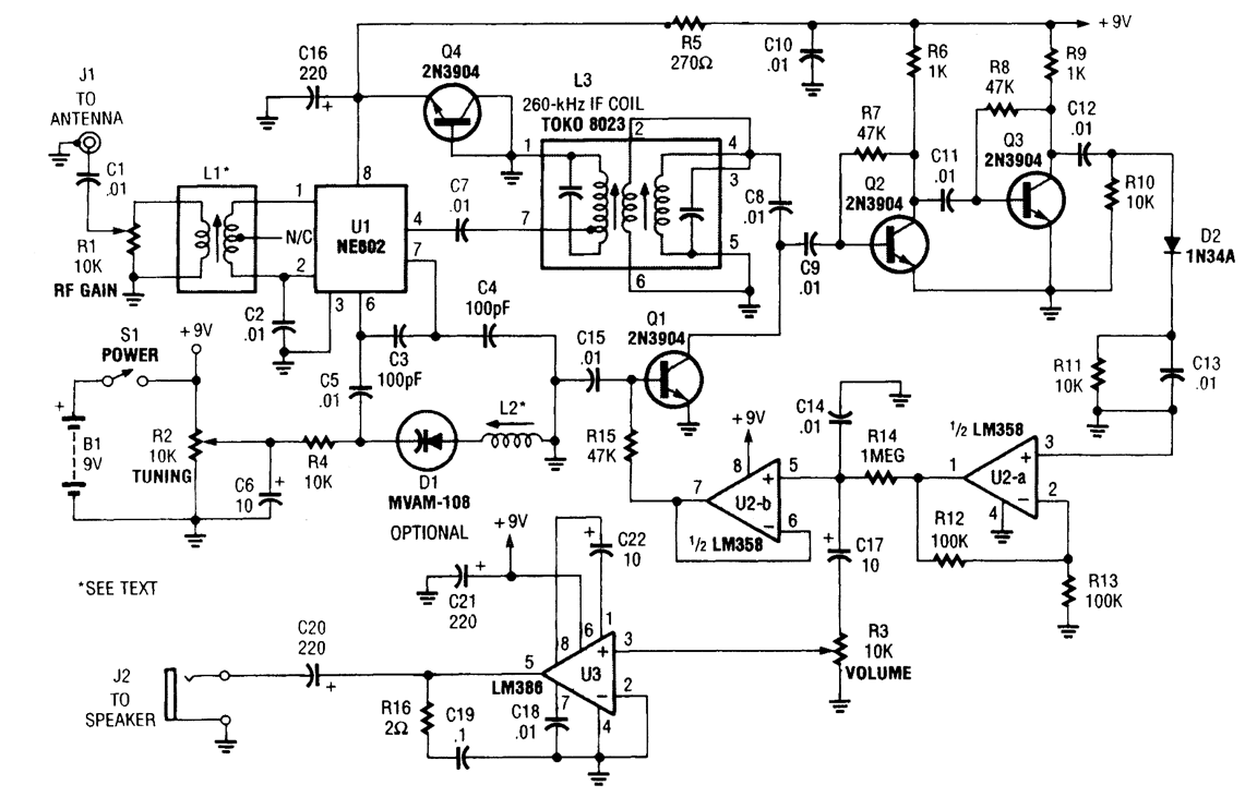
The integrated circuit U1, which is an NE602 double-balanced mixer, functions as both an oscillator and a frequency mixer. Signals received from the antenna input at J1 are transmitted through a DC-blocking capacitor C1 to the RF-gain control resistor...
The documentation and code cleaning for the Jaycar Thermor/BIOS branded wireless weather station receiver has been completed. The code is based on the Practical Arduino weather station receiver project. The process involved analyzing the RF signal from the weather...
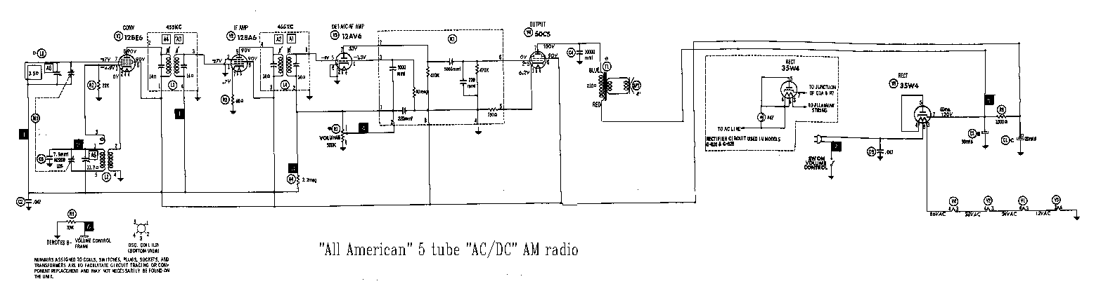
Nearly all AM radio manufacturers utilized this specific circuit from approximately 1948 to 1963. There is a growing interest in collecting these radios as antiques. Credit for the creator of this figure and caption is sought, but the source...
Warning: include(partials/cookie-banner.php): Failed to open stream: Permission denied in /var/www/html/nextgr/view-circuit.php on line 713
Warning: include(): Failed opening 'partials/cookie-banner.php' for inclusion (include_path='.:/usr/share/php') in /var/www/html/nextgr/view-circuit.php on line 713