
1 KW Power (Watt) Meter
This wattmeter circuit is designed to accurately measure electrical power in a range of up to 1 kW, making it suitable for various applications where power consumption needs to be monitored. The circuit operates effectively within a voltage range of 117 Vac ±50 Vac, which allows for flexibility in usage. It is particularly notable for its simplicity, utilizing a single transistor to achieve the desired measurement functionality.
The circuit is engineered to measure power only during negative cycles, which may limit its application in certain scenarios but ensures that it captures the relevant data for specific load types. The absence of an external power supply is a significant advantage, as this feature enhances portability and ease of use. The circuit's idle power consumption is minimal, drawing only 0.5 W, which is beneficial for energy efficiency.
In terms of performance, the circuit has a load current sensing voltage of 10 mV, indicating its sensitivity to small variations in current. Additionally, it exhibits a load voltage loss of just 0.01%, highlighting its efficiency in power measurement. The circuit excels in rejecting reactive load currents, with a rejection ratio exceeding 100:1 for linear loads. This characteristic is crucial for accurate power measurement, as it minimizes the influence of reactive components in the load.
The nonlinearity of the circuit is approximately 1% of full scale when using a 50 A meter movement, which is acceptable for many practical applications. To further enhance accuracy, a copper shunt can be integrated into the design. This shunt compensates for temperature-induced variations in resistance, ensuring that the gain remains consistent across different operating conditions.
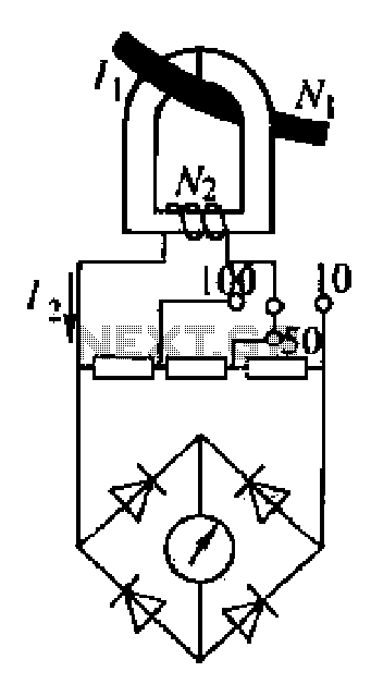
In summary, this wattmeter circuit represents a robust solution for measuring true power in various electrical applications. Its design emphasizes simplicity, efficiency, and accuracy, making it a valuable tool for both hobbyists and professionals in the field of electronics.This watt-meter circuit has measurement range up to 1-KW. This circuit can give the complete (X)(Y) function although uses only one transistor. Actually, this circuit is used for 117 Vac ±50 Vac operation. For lower or lower voltage, this circuit can be modified easily. This circuit only measure power on negative cycles. The advantages of this cir cuit is this circuit does not need external power supply. This circuit measures true power that is delivered to the load. Here is the schematic diagram of the circuit:At idle section, this circuit draw only 0. 5W. This circuit has load current-sensing voltage of 10mV and load voltage loss of 0. 01%. For linear loads, Rejection of reactive load currents is better than 100:1. When using a 50- A meter movement, the nonlinearity of this circuit is about 1% full scale. Copper shunt can be used to give correct gain due to temperature. Be the first of your friends to get free diy electronics projects, circuits diagrams, hacks, mods, gadgets & gizmo automatically each time we publish. Your email address & privacy are safe with us ! 🔗 External reference
Related Circuits
This is the voltage converter to get the voltage of ±1.25-30V from the input voltage of ±35V. I am using the 3 terminal voltage regulator for the voltage to be changed in this unit. As the regulator, LM317 is...
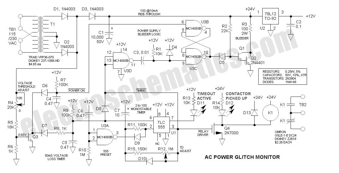
This AC Power Monitor continuously monitors the AC power line voltage for under-voltage conditions and missing cycles. When it detects a total of 5 or 6 consecutive anomalies, it triggers an alert. The AC Power Monitor is designed to provide...
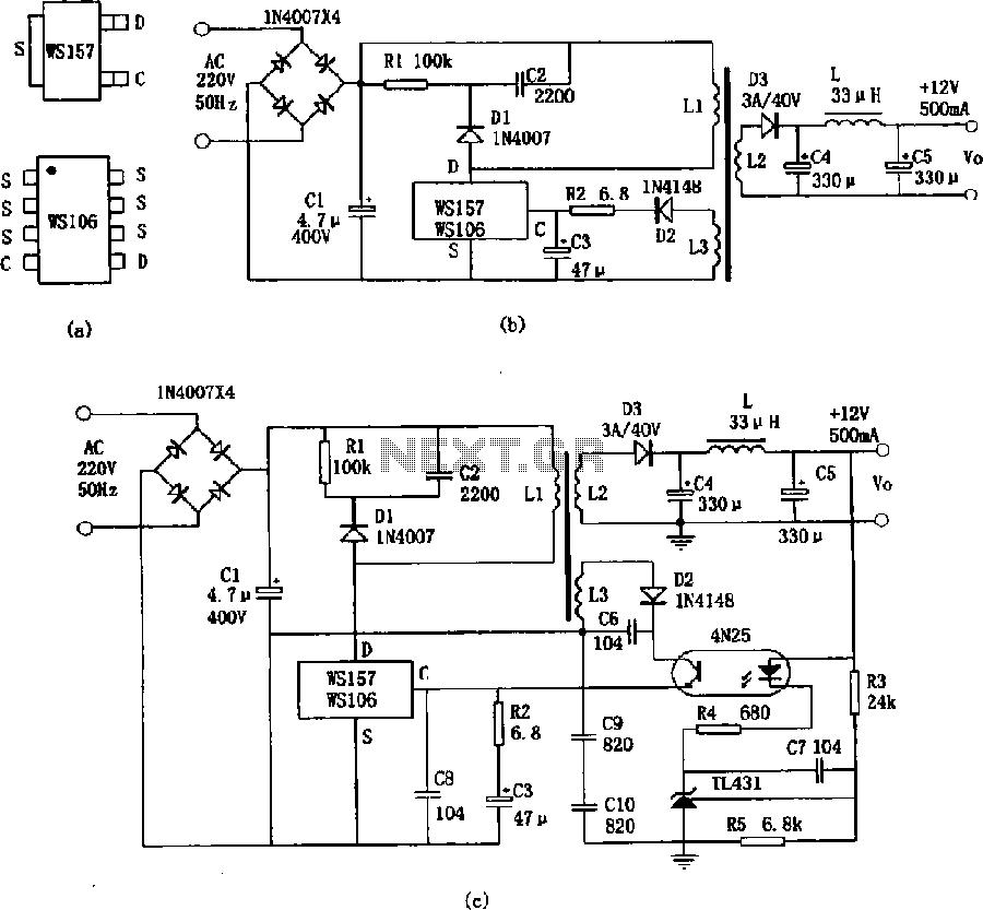
The WS157 or WS106 is a low-power miniature switching power supply that has been developed in recent years. It functions as a regulated switching power supply control device, featuring integrated internal control circuitry and power switches on a single...
An ammeter measures current in a circuit, requiring the circuit to be interrupted in series for measurement. A clamp meter, however, allows for direct measurement of current without breaking the circuit. The clamp meter's structural principle relies on a...
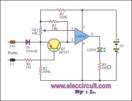
This circuit is capable of measuring voltages up to 15 volts, utilizing a 9-volt battery that draws a current of only 23 mA. The input circuit includes a diode for protection. The circuit design features a voltage measurement system that...
The current handling capability of a power supply system often needs to be checked. Finding a high power-rated variable resistor to provide variable load testing is essential. To effectively assess the current handling capability of a power supply system, the...