
100 V output with shunt regulationl
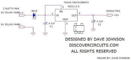
This comprehensive overview outlines various power supply circuits utilizing different integrated circuits (ICs) for specific applications. The 7805 IC provides a reliable method for generating low-voltage outputs suitable for small electronic devices, while the LM317L IC serves high-voltage applications, allowing for a broader voltage range. The LM380 audio amplifier circuit highlights the importance of internal biasing for stability and accuracy in output performance, particularly in audio applications. The fast response protection circuit is critical in safeguarding against overvoltage conditions, ensuring the longevity of connected components. The LM117 adjustable regulator offers flexibility in output voltage and current, making it ideal for varied applications requiring precise control. Lastly, the lead-acid battery charger emphasizes the importance of controlled charging methods to prolong battery life and prevent damage. Each circuit design incorporates essential protective features and operational parameters to meet specific electrical requirements, showcasing the versatility and functionality of modern electronic components.This power supply based 7805 IC regulator, it can provides a regulated output voltage of between 5 V to 15 VDC, it is adjusted and set by a preset resistor. Maximum output current range of this power supply is 350 mA, its enough to supply powered calculator, radio, or cassete player.
An integrated circuit regulates the output voltage and although this 7805 IC is generally applied to a fixed-voltage of 5 Vdc supply it is for a variable output voltage. (View) This is precision high voltage regulator circuit diagram based 3 terminal adjustable regulator LM317L IC.
The circuit require input voltage Vin ‰¥ 178V and can provide output voltage ( V out) between 8 V to 160 V @ 25 mA current output. (View) This split power supply circuit uses the of the popular LM380 audio power amplifier chip. The device is internally biased so that without having any input the output is held midway between the supply rails.
R1, that will be initially set to mid-travel, is used to nullify any inbalance in the output. Regulation of Vout depends upon the circuit feeding the LM380, but negative and positive outputs will track accurately irrespective of input regulation and unbalanced loads. The free air dissipation slightly more than 1 watt, and so will require extra cooling. The device is fully protected and will shut-down if its rated dissipation is exceeded. Current limiting occurs when the output current is higher than 1. 3 A. The split power supply input voltage should never exceed 20 V. (View) This Fast response power supply protection circuit is used to protect regulated power supply from the risks of undervoltage and overvoltage condition.
When working with a regulated power supply to reduce a supply voltage, there`s always the risk that component failure in the power supply may cause a severe overvoltage condition through the load. To deal with overvoltage conditions, the Fast response power supply protection circuit is designed to protect the load underovervoltage conditions.
Component values given are for a 20 V supply with regulated output at 12V. The zener diode can be changed-according to any voltage is to be the maximum. When the voltage at the regulator output goes up to 13 V or higher, the zener diode breaks down-and triggers-the thyristor which will shorts out the supply line and blows the main fuse. (View) This circuit variable power supply with adjustable current limit using three terminal adjustable regulator LM117 which is used to regulate current and the voltage limits.
Variable power supply input range is between 32 V to 40 VDC and can provide outputs up to 25 VDC and provide currents up to 1. 2 A Dioda D2 and D3 and Q2 are added to allow adjustment of output voltage to 0 volts. D1 protect both LM117 during an input short circuit (View) The Lead Acid battery charger is based at charging voltage 2.
4 V per cell, according to many manufacturers recommendations`. Pulse circuit the battery under charge with 14. 4 V (6 CEUs x2. 4 V per cell) at 120 Hz. This Lead Acid battery charger design provides current limiting to protect the internal components battery charger circuit while limiting the charging rate to prevent severe damage to discharged lead-acid batteries. The recommended maximum charging time is typically about a quarter of the value of ampere-hour battery.
For example, the maximum battery charging current to an average of 44 ampere-hour is 11 A. If the impedance of the load requires a larger charging current of 11 A current limit, the circuit will go into current limit. The amplitude of the charging pulse is controlled to maintain maximum peak charging current of 11 A (8 on average A).
(View) With adjustable voltage regulator the circuit voltage can be obtained varies from 7 to 20 VDC. This circuit requires a voltage input> = 20VDC Circuit NotesThe addition of an op amp MC1741 allows adjustment to higher or intermediate values while retaining regulation characteri
🔗 External reference
Related Circuits
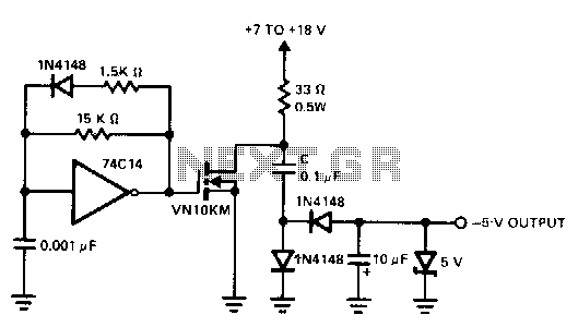
A charge pump is a straightforward method for generating a low-power voltage supply of opposite polarity from the main supply. The 74CL4 IC serves as a self-oscillating driver for the MOSFET power switch, producing a pulse width of 6.5...
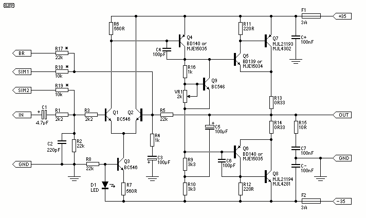
The output devices are MJL4281A (NPN) and MJL4302A (PNP), and feature high bandwidth, excellent SOA (safe operating area), high linearity and high gain. Driver transistors are MJE15034 (NPN) and MJE15035 (PNP). All devices are rated at 350V, with the power...
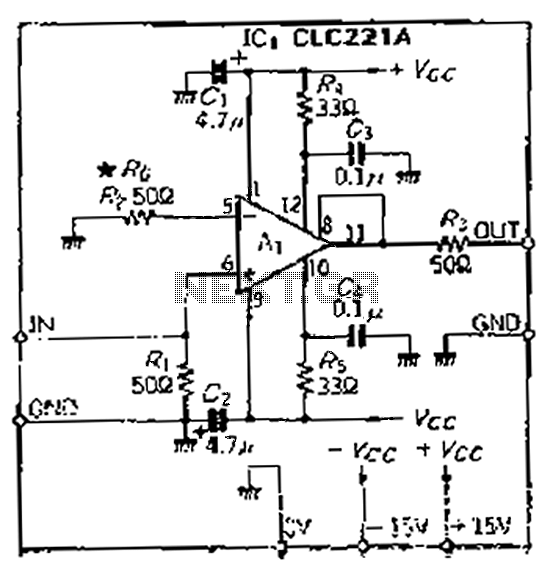
The CLC221A is designed with a traditional operational amplifier (OP) configuration. It is a high-performance current-feedback amplifier capable of operating in both non-inverting and inverting modes. The amplifier features a flat-rate characteristic, which is particularly effective when configured in...
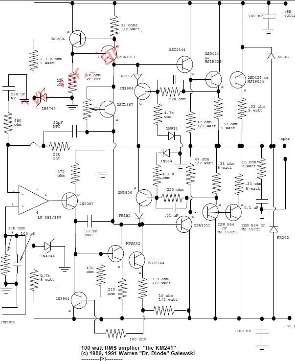
This is a 100-watt basic power amplifier designed to be relatively easy to build at a reasonable cost. It offers better performance, or musical quality, than the standard STK module amplifiers commonly found in mass-market stereo receivers. The design...
This is a tutorial, and the creator has experience with making tutorials. The tutorial aims to provide guidance on a specific topic, leveraging the creator's previous experience in producing instructional content. The focus will likely be on delivering clear and...
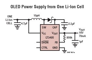
The LT3495, LT3495B, LT3495-1, and LT3495B-1 are low-noise boost converters equipped with an integrated power switch, feedback resistor, and output disconnect circuitry. These devices manage power delivery by adjusting both the peak inductor current and the switch off-time, resulting...