
100Mhz-vhf-crystal-oscillator
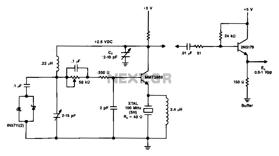
The diagram illustrates a 100 MHz oscillator functioning on the fifth harmonic. To preserve the transistor's gain, it is important to note the increase in the collector's load resistance, Rl, due to the rise in the quartz crystal's internal series resistance, R5. A capacitor, C3, is required at frequencies exceeding 50 MHz to counteract the shunting effect of LL on Rl, thereby maintaining a high load resistance for the transistor and ensuring sufficient gain for oscillation. Furthermore, the equivalent series load across the crystal is composed of an 8.2-ohm RL and a 200 pF CL.
The described oscillator circuit operates at a frequency of 100 MHz and utilizes the fifth harmonic of the resonant frequency of a quartz crystal. The design focuses on optimizing the transistor's performance by addressing the load resistance and internal series resistance of the crystal. The increase in the collector load resistance, Rl, is a critical aspect, as it directly affects the gain of the transistor.
In this configuration, the quartz crystal's internal series resistance, R5, plays a significant role in determining the overall impedance seen by the transistor. As R5 increases, Rl must also be adjusted to ensure that the transistor remains in its optimal operating region, allowing for effective amplification of the oscillation signal.
The inclusion of capacitor C3 is essential for frequencies above 50 MHz. Its primary function is to eliminate the shunting effect caused by the inductive component (LL) across Rl. This shunting effect can lead to a reduction in the effective load resistance, which in turn diminishes the gain of the oscillator. By tuning out this effect, C3 helps maintain a high load resistance, ensuring that the transistor can achieve the necessary gain for stable oscillation.
The equivalent series load across the crystal, comprising an 8.2-ohm resistor (RL) and a 200 pF capacitor (CL), further influences the performance of the oscillator. The resistance RL represents the resistive losses in the crystal, while the capacitance CL accounts for the reactive components of the load. Together, they form a critical part of the oscillator's feedback network, impacting the frequency stability and overall efficiency of the circuit.
In summary, the design of this 100 MHz oscillator is carefully crafted to balance the various elements of the circuit, ensuring optimal performance through the management of load resistance and the tuning of reactive components. This approach facilitates robust oscillation at high frequencies, making it suitable for various applications in communication and signal processing.Diagram shows a 100MHz oscillator operating on the fifth harmonic. Again to maintain the transistor"s gain, note the increase in the collector"s load resistance Rl because of the increase in the quartz crystal"s internal series resistance R5. C3 is needed at frequencies above 50 MHz to tune out the shunting effect of LLon Rl, to maintain a high load resistance for the transistor and get enough gain for oscillation.
The equivalent series RLCL load across the crystal is 8.2ohm (RL) and 200 pF (CL)· 🔗 External reference