
12/24/48 V D.C. Tester
The described tester serves as a versatile tool for diagnosing electrical circuits, particularly in marine applications. It incorporates a simple yet effective design that allows for easy adaptation to various voltage levels through resistor selection. The use of test clips or crocodile clips facilitates secure connections to the voltage rails, ensuring reliable measurements.
The circuit typically consists of a power supply section, LED indicators, and a resistor network. The power supply provides the necessary voltage for the operation of the LEDs and the measurement circuitry. The resistor values play a critical role in setting the voltage range for the tester. By selecting appropriate resistor values, the tester can be configured for 12 V, 24 V, or 48 V systems, thereby enhancing its utility across different applications.
The LED indicators are crucial for providing visual feedback during testing. The red LED signals a positive voltage, while the green LED indicates a negative voltage. This dual-indicator system allows users to quickly assess the voltage status at the test point. In addition to standard voltage testing, the ground-leak testing feature is particularly beneficial in identifying potential safety issues within the electrical system. By detecting leakage to earth potential, the tester aids in ensuring the integrity of the electrical installation.
Overall, this tester is an essential instrument for anyone working with electrical systems in pleasure craft, offering both functionality and adaptability to meet various testing needs.The present tester is intended primarily for testing the 24 V electrical circuits found on most pleasure craft. However, if the resistors are given different values, the circuit may, of course, be used for other voltage ranges.
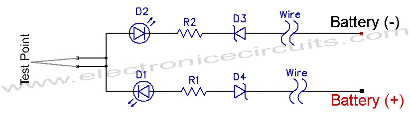
For 12 V, the value of the resistors should be 1. 2 k, and for 48 V, 4. 7 k. The tester should be connected to the +ve an d ve voltage rails with test clips or crocodile clips, whereupon the test probe is placed on the point to be tested. When the potential at the point is positive, the red LED lights; if it is negative, the green one does.
If the supply is not connected to earth, the tester may be used as ground-leak tester. In this situation, one of the LEDs lights when the test probe touches a point at earth potential and there is a leakage. 🔗 External reference
Related Circuits
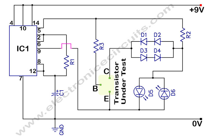
In a circuit transistor tester schematic, there is a circuit that can indicate the condition of a transistor using two LEDs. A good NPN transistor... The circuit transistor tester is designed to evaluate the functionality of both NPN and PNP...

Vasilis Stergiopoulos has developed an RJ45 LAN cable tester. The circuit was initially designed to utilize a 555 timer and a 4017 decade counter IC, but Vasilis has released a schematic and assembly source code for implementing the Attiny2313...
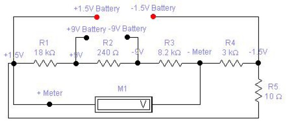
The circuit diagram of a DC battery tester designed by Matthew B. This circuit can measure DC batteries ranging from 1.5V to 9V. Component Parts List: R1 = 18K Ohm, R2 = 240 Ohm, R3 = 8.2K Ohm, R4...

The PACO C-25 differs from the Healthkit IT-22b in that it tests both regular and electrolytic capacitors and utilizes a 40 MHz oscillator to allow a rough measurement of capacitance through a bridge circuit. In vintage vacuum tube equipment,...

This circuit performs a rapid battery test without requiring a power supply or costly moving-coil voltmeters. It features two ranges: when SW1 is configured as depicted in the circuit diagram, the device can test batteries ranging from 3V to...
12V Vehicle Electrical Wiring Tester Circuit. This tester is useful for checking vehicle electrical circuits. Two LEDs indicate whether the circuit is live or not. The 12V vehicle electrical wiring tester circuit is designed to provide a simple yet effective...